Design of Sediment Trapping System
Sediment traps
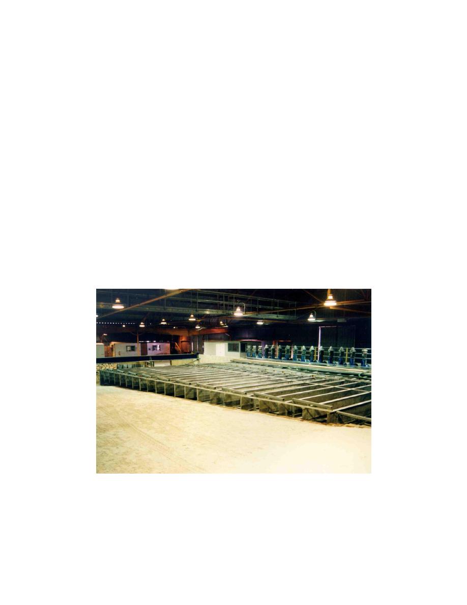
The sediment traps are located at the downdrift end of the facility, and are
positioned within the flow channels, as illustrated in Figure 20. A sediment trap
is located in each flow channel starting with Channel No. 1 (the most shoreward
flow channel) and extending offshore to flow Channel No. 17. Additionally, a
sediment trap is located in flow Channel No. 19. The decision to eliminate traps
in flow Channels No. 18 and 20 was determined based on cost considerations and
the expected low rates of longshore sediment transport in the offshore region.
Based on the fall velocity of the sediment used to construct the moveable-bed
beach, and the magnitude of the longshore current in the flow channels, the
decision was made to maximize the length of these sediment traps. Each trap is
approximately 6.0 m long and 0.6 m wide. In addition, two shorter traps are
located landward of flow Channel No. 1 with the objective of quantifying the
longshore sediment transport rate near the still-water shoreline and in the uprush
zone. Each "uprush-zone " trap is approximately 2.5 m long and 0.5 m wide.
These two traps were added to the design after qualitatively observing the
magnitude of longshore sediment transport in the swash zone as well as the
morphologic changes that occurred in this region during some preliminary
moveable-bed experiments.
Figure 20. Twenty sediment traps are located inside downdrift flow channels
The dimensions and capacity of each of the traps are tabulated in Table 2,
based on the as-built inside dimensions of each trap and assuming that the traps
can be completely filled with sand along the entire length of the trap (a very
extreme case). The last column lists the capacity of each trap in terms of the
36
Chapter 4
Sediment Trapping and Dredging Systems


 Previous Page
