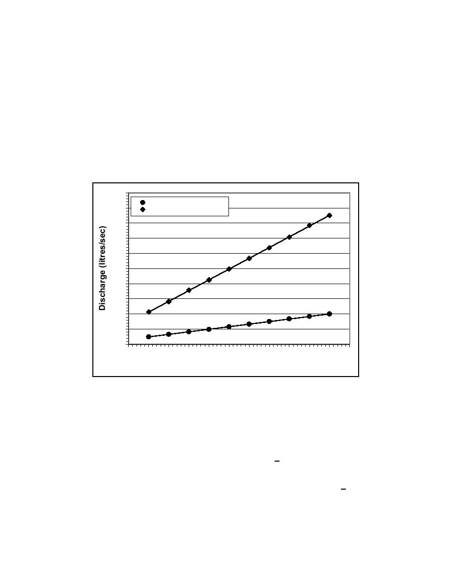
Figure 19 shows the results for pump-and-piping System No. 10. The lower
curve represents the relationship between pump discharge and frequency of the
motor controller when water is flowing past the flow meter in the smaller
pipeline (50-mm diam). The upper curve represents the second series of tests
with water flowing past the flow meter in the larger pipeline (100-mm diam).
The two best-fit lines passing through the two sets of data represent the results
from regression analysis. The relationship between pump discharge and
frequency was very linear, as predicted by theory. This was true for the 20
systems. As listed previously in Table 1, several of the systems have identical
pumps, motors, and variable frequency motor controllers. However, because the
length of each pipeline varies for each system, the discharge rates at a given
frequency for each of these systems are not identical. Therefore, there is a
unique set of calibration curves for each of the 20 systems.
100
Diameter = 50 mm
90
Diameter = 100 mm
80
70
60
y = 1.4199x - 0.0189
50
R2 = 0.9999
40
y = 0.3375x - 0.1813
30
R2 = 0.9998
20
10
0
10
15
20
25 30 35 40 45 50 55
60
65
Motor Controller Frequency (Hz)
Figure 19. System No. 10: Relationship between pump discharge and frequency
of the motor controller
Using these calibration curves, the operator of the facility can readily
determine the frequency settings for each of the pumps, once the desired
discharge rate for each system has been determined. Two years after conducting
these calibration tests, at the time of writing this report, experience has shown
that these calibration curves have an accuracy of within +2 to 3 percent.
Therefore, these calibration curves work very well as a first approximation of the
frequency settings of the motor controllers. The facility operator then would
adjust the frequency settings to bring the measured discharge rates to within +1
percent of the desired values. After the low-flow or the high-flow mechanisms
have been selected for each pump, the process of converging in on the correct
frequency for the motor controllers requires approximately 30 min.
32
Chapter 3
Longshore Current Recirculation System


 Previous Page
