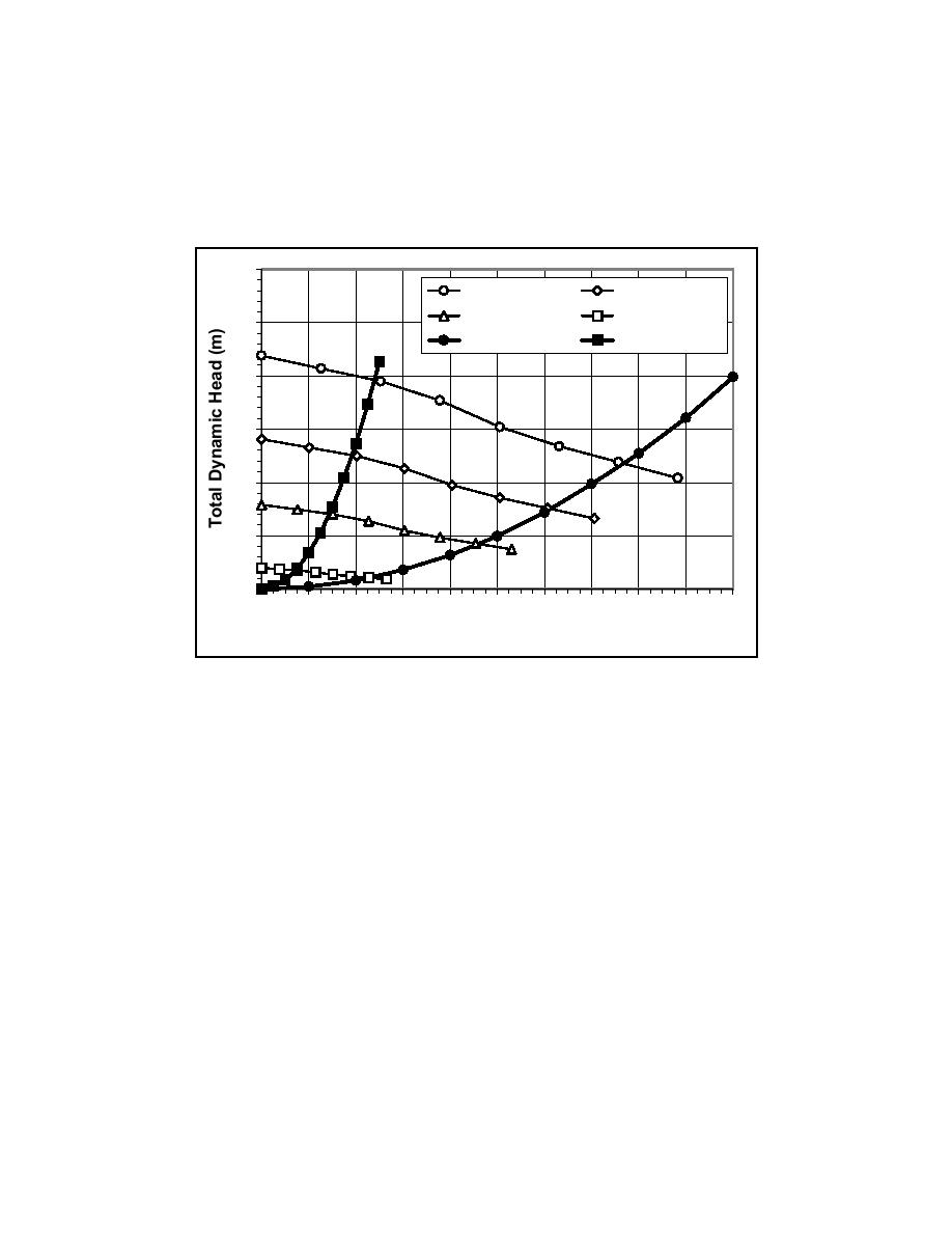
(Point No. 3) on the second characteristic pipe curve. To obtain lower flow
conditions, the pump discharge can again be reduced until Point No. 4 is reached,
corresponding to 30 percent of the nominal speed. At Point No. 4, the discharge
through the piping system is approximately 7.5 ℓ/sec, which is 10 percent of the
maximum discharge of 75 ℓ/sec, at Point No. 1. The 20 pump-and-piping
systems were designed to have this same functional capability.
30
1800 RPM
1440 RPM
1080 RPM
540 RPM
25
FS = 100 mm
FS = 50 mm
20
3
15
1
10
1
5
4
2
0
0
10
20
30
40
50
60
70
80
90
100
Flow Rate (litres/sec)
Figure 18. System No. 10: Pump performance and characteristic pipe curves
Calibration and Testing
Relationship between pump discharge and frequency
After the recirculation system was constructed, tests were conducted to
develop a relationship between pump discharge rates and frequency of the motor
controllers for each of the 20 pump-and-piping systems. The discharge from
each system was measured using the factory calibration equations supplied with
each of the 40 in-line flow sensors. Tests were conducted starting with low-flow
conditions by closing the valve in the larger pipeline and allowing the flow to
pass through the smaller pipeline. Each system was evaluated for the full range
of frequencies of the motor controllers starting at 15 Hz and increasing up to 60
Hz in increments of 5 Hz, for a total of 10 data points per calibration curve. Each
data point represents the average flow rate measured for 500-sec duration and
sampled at 20 Hz. This series of 10 tests was repeated for the high-flow
conditions by closing the valve in the smaller pipeline and allowing the flow to
pass through the larger pipeline.
31
Chapter 3
Longshore Current Recirculation System


 Previous Page
