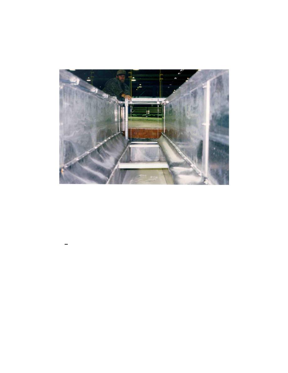
clearance for the instrumentation bridge to traverse over the top of the sediment
traps during calibration of the wave gauges and the profile indicator. This design
also keeps all of the mechanical components below the upper surface of the
support frames thereby eliminating interference with the suction hose of the
slurry pump during the dredging operation.
Figure 22. Stainless steel, splash-proof load cells are bolted to the bottom of the
support frames to support the sediment traps. A neoprene rubber seal
is used between the flow channel walls and the sediment traps
Three different size load cells were used with rated capacities of 250-, 500-,
and 1,000-kg, depending on the design requirements for each trap. The load cells
can temporarily support 150 percent of the manufacturers rated capacities
without experiencing permanent damage. The manufacturer specifies an accuracy
of +0.05 percent of the rated capacities, which includes errors resulting from
linearity, repeatability, and hysteresis. During the testing phase of the prototype
sediment trap, it was concluded that the load cells are very robust with respect to
fluctuations in humidity. However, the load cells are more sensitive to
fluctuations in temperature. Errors induced by temperature fluctuations are
minimized by performing a "shunt-cal" on all 60 load cells, prior to each
experiment, and this procedure will be discussed in Chapter 8.
Figure 23 graphically illustrates the design capacity of each of the sediment
traps. Two series of data are shown in the figure. The first series represents the
maximum capacity of each trap based on the manufacturers rated capacities of
the three load cells supporting each trap. The second series represents the
maximum submerged weight of sand that each trap can hold, based on the
volumetric capacity of each trap. These values are identical to the values listed
in the last column of Table 2. As discussed previously, this assumes that the
traps are completely submerged and completely filled with sand along the entire
39
Chapter 4
Sediment Trapping and Dredging Systems


 Previous Page
