along the beach to quantify the alongshore uniformity of the moveable bed. A
fully automated 3-D bathymetric survey system was developed to minimize the
time and effort required to conduct a bathymetric survey. In addition, the system
needed to be amphibious so that changes to the bathymetry above the still-water
level could be accurately measured.
The system consists of two primary components. First, the vertical elevation
of the sand bed is measured using a commercially available beach profile
indicator consisting of a mechanical spring-wheel system which tracks the
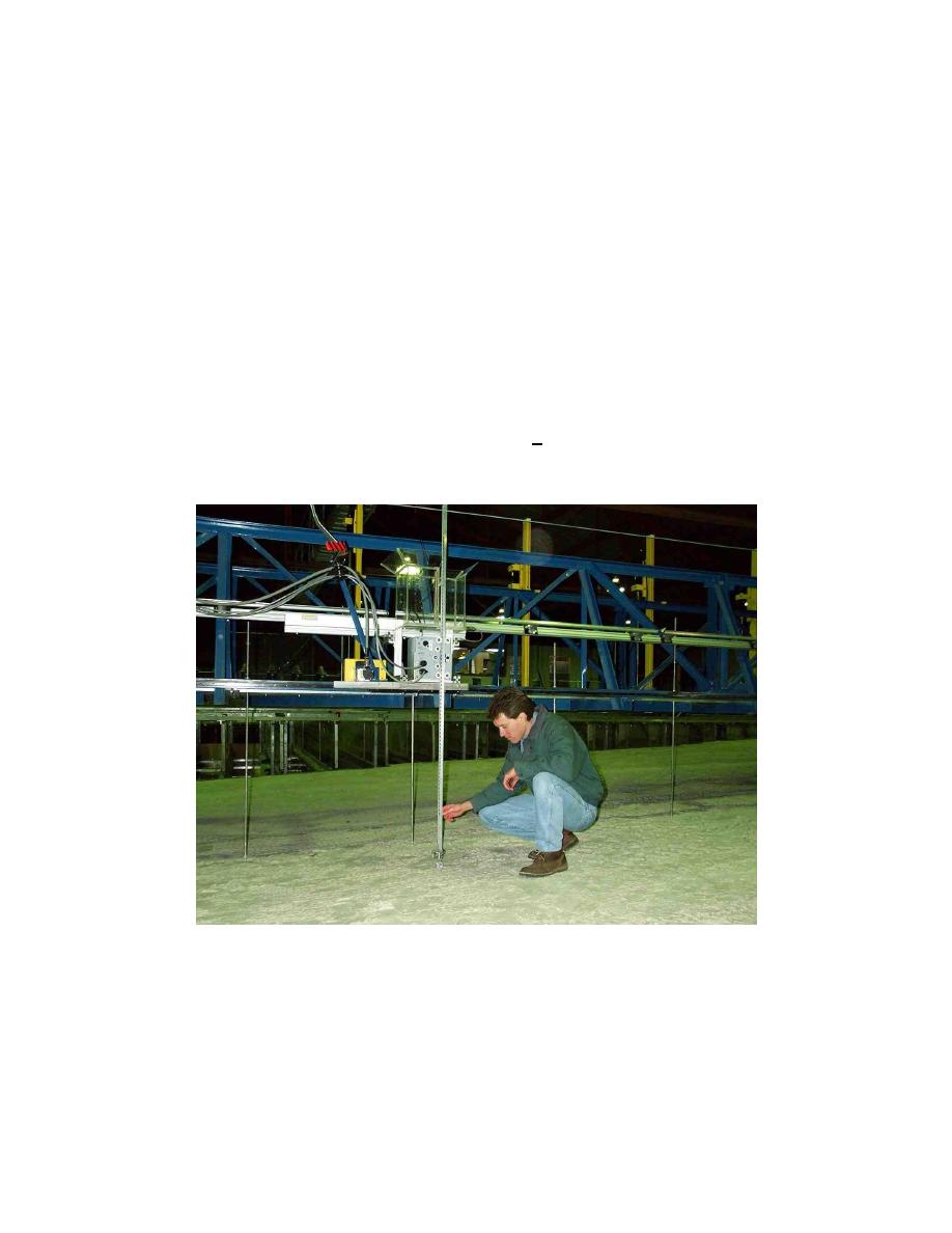
elevation of the bed as the sensor moves along the length of the bridge. Figure 8
shows the profile indicator in a stationary position on the sand bed when the
facility is drained. The spring-wheel assembly is located at the bottom end of the
1.52-m-long vertical rod. As the wheel rolls along the surface of the sand bed at
a constant horizontal speed of 0.1 m/sec, a servomotor maintains a continuous
downward force on the bed equivalent to a mass of 40 g. An analog output
voltage is provided by a potentiometer circuit, which is coupled with the sensor.
This gives a vertical resolution of approximately +1 mm. The sensor has
sufficient sensitivity and frequency response to measure the sand ripples,
although in some instances the wheel slightly rounds off the crest of the ripples.
Figure 8.
Beach profile indicator resting on sand beach with facility drained
The second component is a high-resolution x-y positioning system. A servo-
controlled support platform moves the beach profile indicator along a linear
bearing (cross-shore position) which is mounted to the updrift side of the bridge.
The alongshore location of the beach profiler is controlled with the drive motors
on each end of the bridge which traverse along the support rails on rigid urethane
tired wheels. The position of both the x- and y-axis are controlled using
11
Chapter 2
Overview of the Laboratory Facility


 Previous Page
