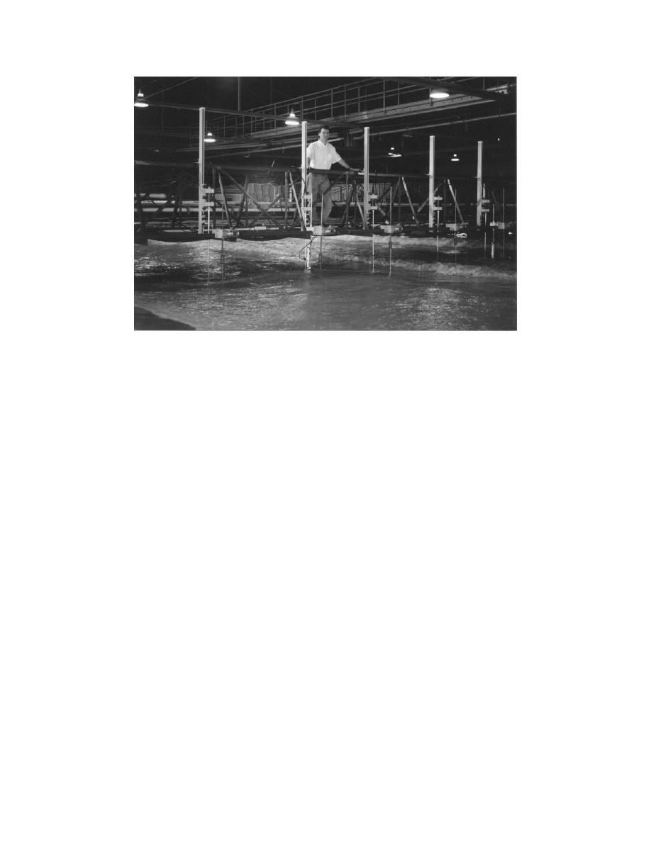
Figure 7.
View of co-located sensors on instrumentation bridge
The bridge spans 21 m in the cross-shore direction and can traverse the entire
length of the wave basin. Each end of the bridge is independently driven along
support rails by a digitally controlled servo-electric drive motor. The bridge has
sufficient strength to support up to 3,000 kg of personnel and equipment evenly
distributed in the cross-shore direction.
For experiments conducted with high-water levels, the underside of the bridge
is located at the nominal elevation of the top of the exterior walls of the wave basin.
However, when the water level is lowered significantly, waves impact the
instruments at a lower elevation resulting in increased deflections and vibrations of
the instruments. To mitigate this potential problem, the bridge was designed to
function at two different elevations. For experiments conducted with low-water
levels the bridge can be lowered by 0.30 m by removing spacers located at each end
of the bridge. Lowering the bridge should decrease deflections and vibrations of the
sensors because the relative height of the bridge above the water level is reduced.
Wave gauges
Water surface elevation time series are simultaneously measured using 14
single-wire capacitance wave gauges. Ten of the wave gauges are mounted along
the length of the instrumentation bridge to measure wave transformation (shoaling,
refraction, wave breaking, and decay) from the offshore zone, across the surf zone,
and into the swash zone. These wave gauges can be seen in the foreground of
Figure 7. The wave gauges can be readily repositioned at any location along the
length of the bridge for various test configurations. The gauges are numbered in
ascending order, starting with Wave Gauge No. 1 near the shoreline, and moving
offshore to Wave Gauge No. 10. The remaining four wave gauges are fixed in an
array along the X = 18-m contour line. One wave gauge is centered in front of
9
Chapter 2
Overview of the Laboratory Facility


 Previous Page
