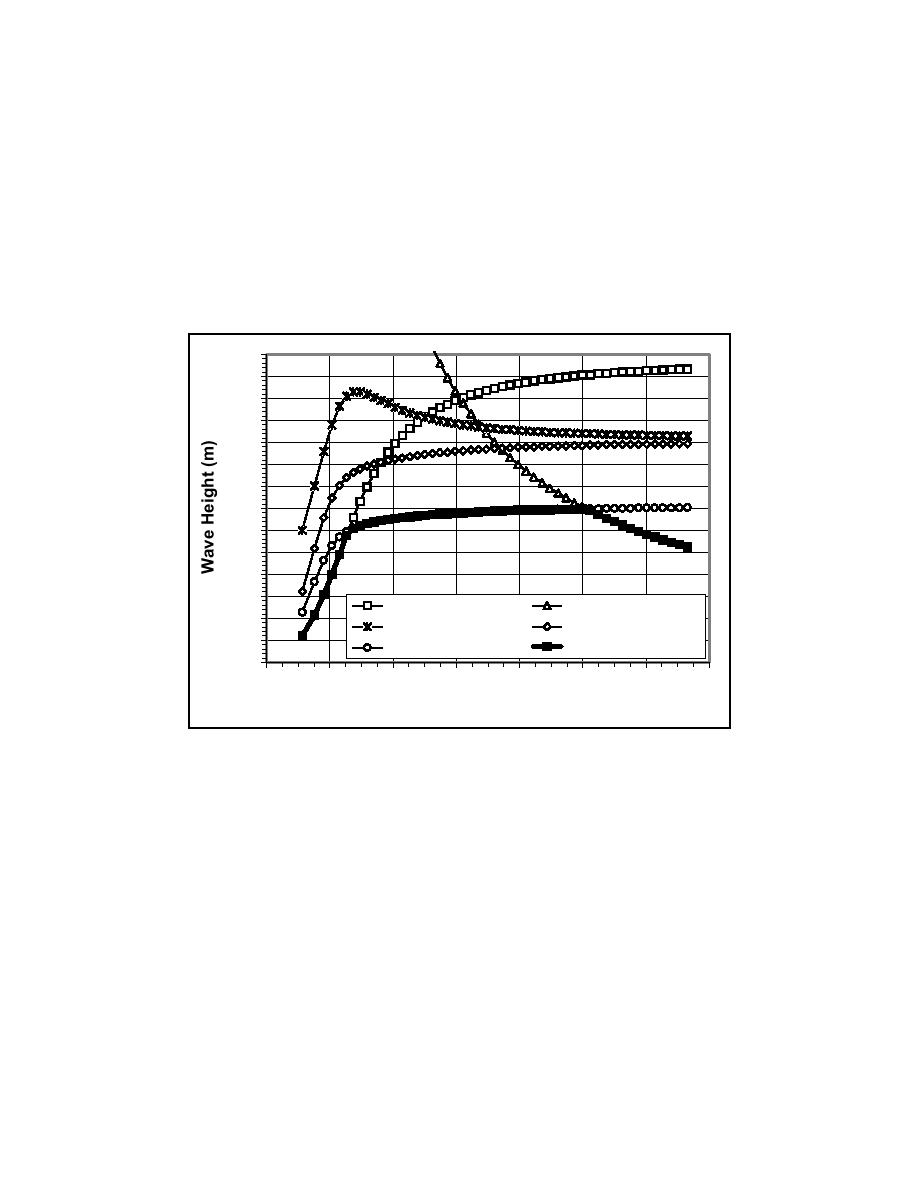
stroke limit, velocity limit, and torque limit curves are based on the maximum
performance of the wave generators for a single regular wave. However,
assuming that regular waves are generated for many minutes or hours of
operation, as would normally be the case, the continuous operation curve is the
maximum performance of the wave generators. The system limit curve is the
lower limit of all of the curves, and represents the maximum regular wave height
that can be continuously generated. In contrast, when generating irregular waves,
the maximum wave height in the irregular wave train is not limited by the
continuous operation curve. Therefore, the maximum irregular wave height
increases significantly for peak wave periods ranging from T = 2.0 to 3.5 sec.
0.70
0.65
0.60
0.55
0.50
0.45
0.40
0.35
0.30
0.25
0.20
0.15
Cresting Limit
Stroke Limit
0.10
Velocity Limit
Torque Limit
0.05
Continuous Operation
System Limit
0.00
0.0
1.0
2.0
3.0
4.0
5.0
6.0
7.0
Wave Period (sec)
Figure 6.
Performance of wave generators for a water depth of 0.9 m
Instrumentation Bridge
A semiautomated instrumentation bridge is used to traverse the length of the
testing region to allow detailed measurement of waves, currents, sediment
concentration, and beach profile evolution. The bridge provides a rigid platform
for mounting wave gauges, current meters, fiber-optic backscatter sensors, and a
fully automated bathymetric survey system. Figure 7 is an oblique view of the
downstream side of the bridge, looking in the offshore direction, during a
moveable-bed experiment. For a typical experiment, wave gauges and acoustic
doppler velocitimeters are co-located to provide wave and current data at the
same cross-shore location. The wave gauges and current meters are separated by
approximately 40 cm, in the longshore direction, to avoid hydraulic and electrical
interference between the two different types of instruments. The bridge also
functions as an observation platform and provides access for personnel to
manually adjust the cross-shore and vertical position of the instruments.
8
Chapter 2
Overview of the Laboratory Facility


 Previous Page
