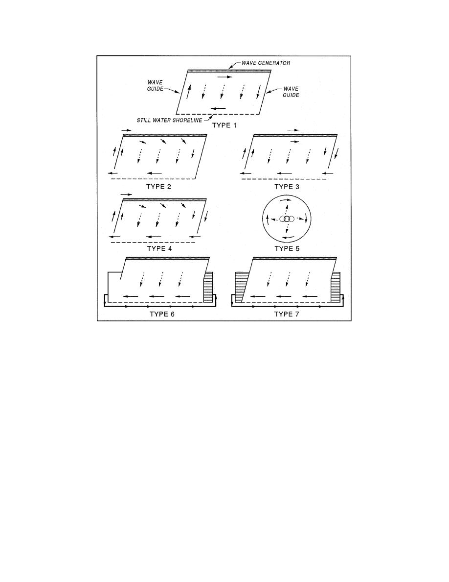
Figure 10. Seven types of longshore current recirculation systems. Illustration of
Types 1 through 5 reproduced from Figure 1 (Visser 1991) (Dashed
arrows denote wave direction, and solid arrows denote mean current
direction)
Type 3: Brebner and Kamphuis (1963) terminated both the upstream and
downstream wave guides near the breaker point. The recirculation is driven by a
water level difference between the upstream and downstream ends of the facility.
Type 4: Kamphuis (1977) used a procedure almost identical to Type 3,
except that the wave generators were raised slightly above the basin floor and
allowed the longshore current to also reenter the testing region beneath the wave
generators.
Type 5: Dalrymple and Dean (1972) used a circular wave basin with spiral
wave generator and a circumferential beach. This is a unique method of avoiding
the traditional boundary effects resulting from the upstream and downstream
lateral boundaries of a wave basin.
15
Chapter 3
Longshore Current Recirculation System


 Previous Page
