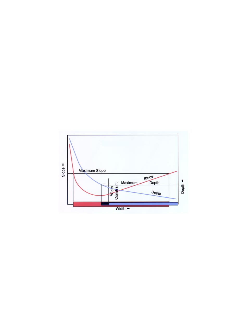
depth could also be a constraint. Depth is not plotted in Figure 6.18, but it is
calculated for each slope and width combination determined. With constraints,
the range of solutions is reduced, see Figure 6.19.
Different water and sediment discharges will produce different stability
curves. First, the stable channel solution is obtained for the channel-forming
discharge. Then, stability curves are calculated for a range of discharges to
determine how sensitive the channel dimensions are to variations in water and
sediment inflow events.
The stable channel dimensions are calculated for a range of widths on either
side of a prescribed median value. (A median value can be prescribed, manually,
on the GC record, but not in SAMwin.) If no median value is prescribed, the
program assigns a value based on the following hydraulic geometry equation,
proposed in EM 1110-2-1418 (USACE 1994).
B = 2.0 Q0.5
Figure 6.19. Slope-width graph showing the effect of constraints on the range of
solutions.
The SAM program assigns 20 base widths for the calculation, each with an
increment of 0.1B. Calculations for these conditions are displayed as output.
Stability curves can then be plotted from these data.
A solution for minimum stream power is also calculated by the model. This
solution represents the minimum slope that will transport the incoming sediment
load. Solution for minimum slope is obtained by using a second-order
Lagrangian interpolation scheme. Opinions are divided regarding the use of
120
Chapter 6
Input Requirements and Program Output for SAM.hyd


 Previous Page
