and φ represents the variables (η, uα, vα). The finite-difference operator defini-
tions in Equation 27 corresponding to the x and y components of the momentum
equation are centered at (i+1/2,j) and (i,j+1/2), respectively.
The finite difference formulation of the continuity equation (Equation 21)
yields an algebraic equation that is explicitly solved for η at all grid points. The
formulation for the x and y momentum equations (Equations 22 and 23) have
been decoupled by placing the vxt, vyt, and vxyt terms on the right-hand side of the
x equation and the uxt, uyt, and uxyt terms on the right-hand side of the y equation.
This reduces the momentum equations to tridiagonal equations for uα and vα
along lines in the x and y direction, respectively. Tridiagonal matrices are much
easier to store and solve than the large sparse matrix equation that would be
obtained if the equations were not decoupled. The major disadvantage of this
approach, however, is that the iterative step takes longer to converge for shorter-
period waves propagating at large angles to the grid where the higher-order
derivative terms (uxxt, vyyt).
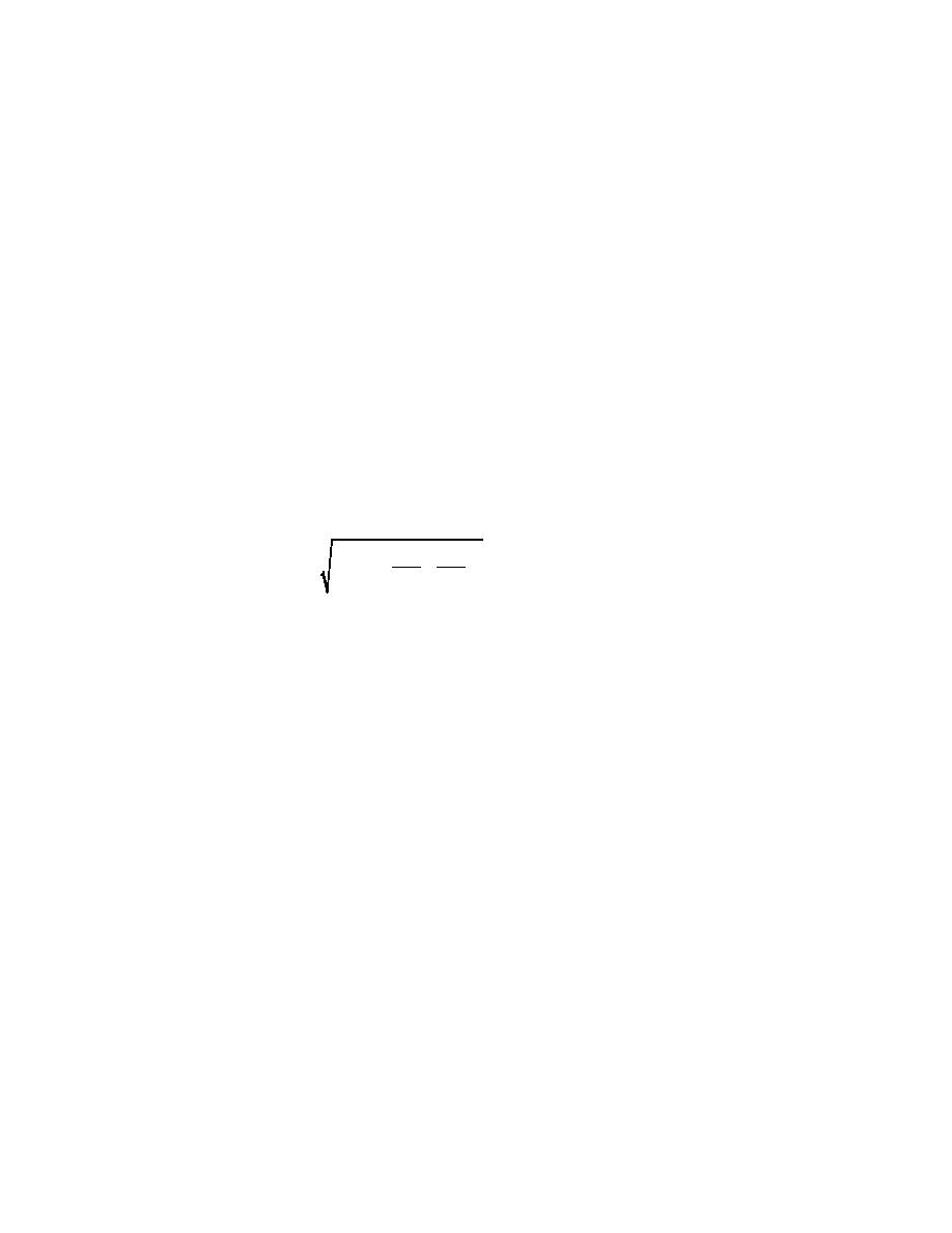
The numerical scheme is stable provided that the Courant number, CR, is less
than 1, i.e.,
2 2 1
1
=
C ∆t 2 + 2
<
1
CR
(28)
∆x
∆y
where C is the phase speed based on the average zero-crossing period of the
incident waves. It is, however, recommended that the Courant number be kept
within the range 0.5 to 0.7 since nonlinear wave-wave interactions, wave break-
ing, and the presence of reflected waves can affect the stability criterion of the
numerical model.
Boundary Conditions
To solve the governing equations, appropriate boundary conditions have to
be imposed at the boundaries of the computational domain. This requires specifi-
cation of waves propagating into the domain and the absorption of waves propa-
gating out of the domain. The equations have also been modified to simulate
wave interaction with fully/partially reflecting structures within the computa-
tional domain. The types of boundaries considered in BOUSS-2D include:
a. Fully reflecting or solid wall boundaries.
b. External wave generation boundaries.
c. Internal wave generation boundaries.
d. Wave absorption or damping regions.
e. Porous structures.
15
Chapter 3 Numerical Solution


 Previous Page
