

704
Stauble and Tabar
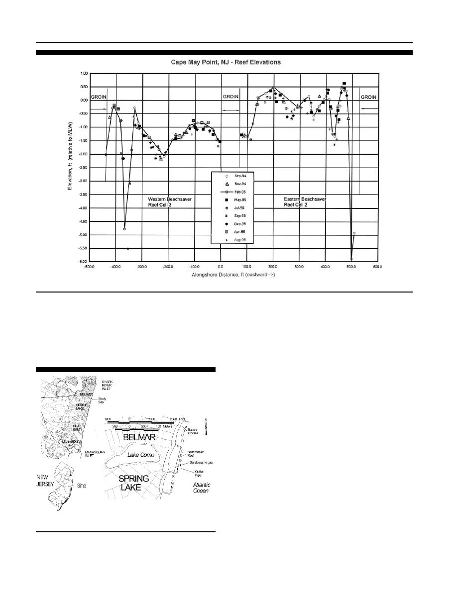
Figure 20. Settlement at Cape May Point Beachsaver Reef (after Herrington et al., 1997).
HERRINGTON et al. (1997) speculated that the trench was
fair weather waves measured. HERRINGTON et al. (1997) sug-
formed due to the bottom return flow being deflected by the
gest that wave heights would decrease even more for larger
base of the reef. This installation was unique in that the reef
storm waves. Dye studies indicated that water exchange oc-
structure was placed high in the water column. It was esti-
curred in concentrated currents along the edge of each groin.
mated that wave heights were reduced by 10 percent for the
The project remains in place, with plans to construct another
Beachsaver Reef in an adjoining jetty compartment, with its
crest at MLW. This new Section 227 monitoring project will
compare if a shallower placement will change the perfor-
mance.
BELMAR/SPRING LAKE, NEW JERSEY, PROJECT
A third installation of the State of New Jersey sponsored
Pilot Reef Project was completed in August 1994 on the bor-
der between the boroughs of Belmar and Spring Lake, NJ.
This area is along the northern New Jersey coast is approx-
imately 32 km (20 miles) south of Sandy Hook (Figure 21).
This area is characterized as a headland coast and is located
between Shark River Inlet and Manasquan Inlet. The net
drift direction is from south to north along this stretch of
coast. Beach erosion has been a constant problem and almost
the entire shoreline is armored by seawalls to protect Ocean
Avenue. Several stone groins around 168 m (550 ft) in length
have been constructed perpendicular to the shoreline to trap
the limited amount of sand available in the littoral system.
The beaches are narrow, with a steep offshore slope. Of the
Figure 21. Location of the Beachsaver Reef installation at Belmar/
three sites in New Jersey, this site has the most energetic
Spring Lake, New Jersey.
wave climate and is about halfway between the two inlets so
Journal of Coastal Research, Vol. 19, No. 3, 2003

 Previous Page
