

ERDC/CHL CHETN- IX-7
December 2001
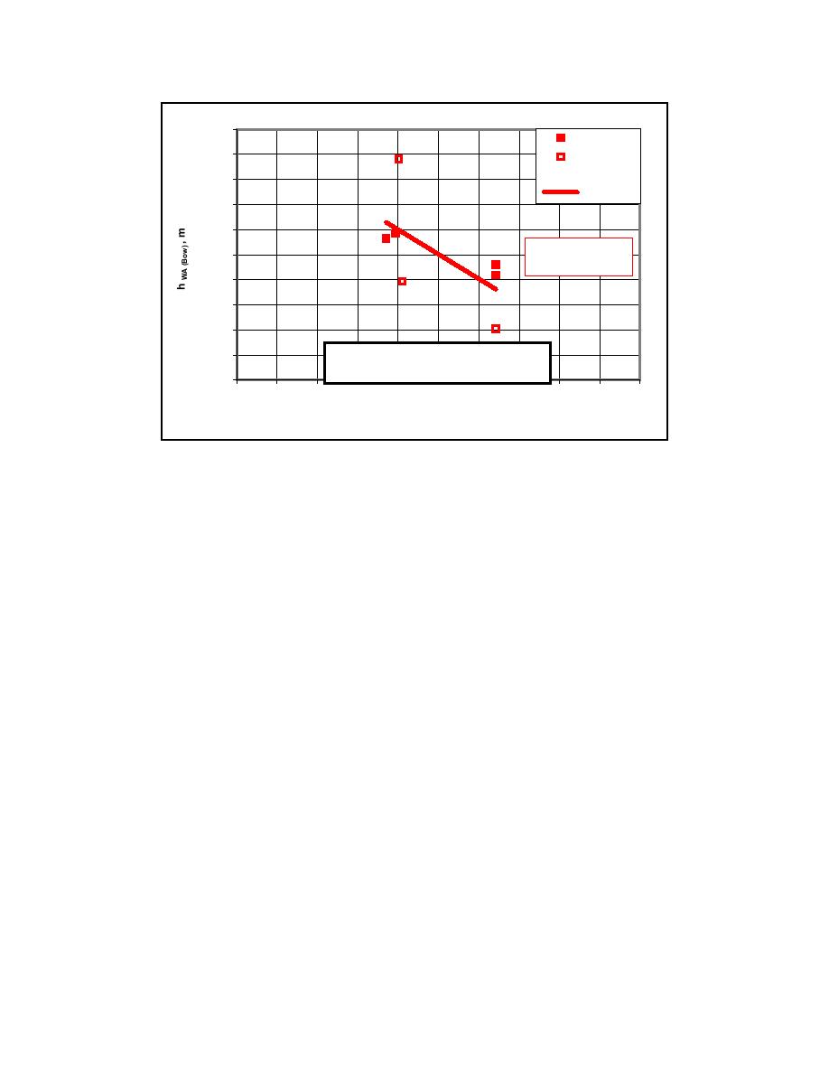
1.00
DDU412
0.90
DDU422
all
0.80
Linear (all)
0.70
0.60
y = -0.098x + 0.9914
0.50
2
R = 0.3885
0.40
0.30
0.20
World Utility - Outbound - hWA at the Bow
0.10
Full load (MAX draft)
0.00
0
1
2
3
4
5
6
7
8
9
10
Speed, knots
Figure 14. Calculated hWA,Bow at the World Utility for outbound runs with full load
(MAX draft). A linear least squares fit is also shown
Example: How does the hWA,Bow at the ship's bow compare to the underkeel clearance hUKC for
the entrance channel? The purpose of this example is not to provide design guidance based on
very limited laboratory data, but rather to show the relationship between the hWA,Bow and hUKC for
this data. This example does show, however, that the laboratory data give reasonable values for
hUKC.
The channel design depth hDC is related to the fully-loaded ship draft T and hUKC by
hDC = T + hUKC
(1)
Rearranging Equation 1 and inserting the existing Barbers Point hDC = 12.8 m and T = 10.9 m for
the World Utility, the maximum available hUKC is only 1.9 m (6.2 ft). This is the maximum
distance between the ship's keel and the seabed for the ships using Barbers Point at this time.
The next step is to compare this maximum available hUKC to the hUKC from the allowances. As
stated previously, the hUKC is composed of the four allowances
hUKC = hWA - hTI + hSQ + hSF
(2)
where,
hWA
= wave-induced motion allowance,
hTI
= tide allowance,
hSQ
= squat allowance, and
16

 Previous Page
