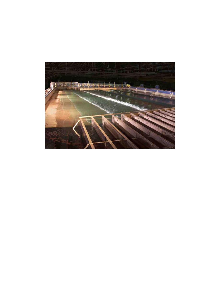
waves. Figure 55 is a photograph of the LSTF taken during a regular wave
experiment. A total of 20 experiments were conducted, each with a different
magnitude and cross-shore distribution of pumped flow rate. Fifteen regular
wave experiments were conducted in the process of determining the proper
magnitude and cross-shore distribution of the longshore current and were
identified as Test 2 (waves only) and Tests 6A-6N (waves and currents). Five
irregular wave experiments were conducted and identified as Tests 8A-8E.
Figure 55. Oblique view of the Large-scale Sediment Transport Facility (regular
wave experiment). A model operator standing in the upper left corner
indicates the physical size of the facility
The incident wave conditions adopted for Tests 6A-N and Tests 8A-E are
given in Table 4, where T is wave period (peak spectral wave period, Tp, for
irregular wave case), H is wave height (energy-based significant wave height,
Hmo, for irregular wave case), λ is wave length, d is still-water depth, θ is the
angle of incidence relative to shore normal, and the subscripts "0" and "1" refer
to values in deep water and at the wave generators, respectively. Deepwater
values were calculated using linear wave theory. For the irregular wave tests,
Hmo was selected so that the root-mean-square wave height, Hrms, was
comparable to the average wave height, Havg, for the regular wave case.
Therefore, the total incident wave energy used for both regular and irregular
waves was similar. For the irregular wave tests, a TMA spectrum was used to
define the spectral shape. The spectral width parameter was 3.3, a value
representing typical wind sea conditions. A random phase method was used to
synthesize the pseudo-random wave train used to drive the wave generators. The
length of the drive signal was 500 sec, duration of 200 times the peak wave
period (2.5 sec). The still-water depth at the wave generators was constant at
0.667 m during all fixed-bed experiments.
102
Chapter 9
Establishing Uniform Longshore Currents


 Previous Page
