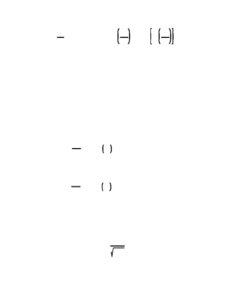
Fundamentals of Engineering Design
2
Fg
D50
D50
log
' &0.2026 % 0.07026 log
% 0.9330 log
(5.10)
*
*
Fg)
and log 0.8 for D50/ $ 2.
Brownlie (1981) summarizes his analysis for flow resistance determination by stating:
for slopes less than 0.006, only upper regime flow is expected. For slopes less than
0.006, the maximum velocity of the lower regime can be determined from Fg = 0.8
Fg& and the minimum velocity of the upper regime from Fg = 1.25 Fg& .
Brownlie's analysis covered a wide range of conditions. His flow resistance equations applied to
sand bed material ranging in size from 0.088 to 2.8 mm. The range of slope used in calibration was
0.000003 to 0.037.
Brownlie's equations relating hydraulic geometry and flow resistance are (5.11), (5.12), and (5.13).
Upper Regime:
RS
0.6248
0.0875
0.08013
' 0.2836 q(S
S
Fg
(5.11)
D50
Lower Regime:
RS
0.6539
0.09188
0.1050
' 0.3724 q(S
S
Fg
(5.12)
D50
where: R
=
hydraulic radius associated with the bed;
D50
=
median grain size;
S
=
slope;
g
=
q
=
unit discharge; for wide channels assumed to be V*D; and
g
=
acceleration of gravity.
q
q( '
(5.13)
gD503
The Brownlie sediment transport equation is used to relate hydraulic geometry to sediment
concentration in the stable channel design method. The equation is taken to be equivalent to concentration
measured as milligrams per liter with an error of less than 1 percent for concentrations
177


 Previous Page
