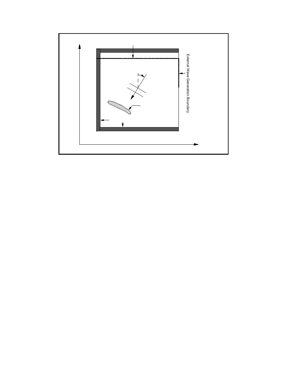
y
Internal Wave Generation Boundary
(x max , ymax)
Wave
Direction
Porous Structure
Damping Regions
( xorigin , yorigin)
x
Figure 6.
Definition sketch for computational grid
a. The grid axes should be aligned as much as possible with the
predominant wave direction.
b. Points of interest in the computational domain should be kept at least one
wavelength away from the boundaries to minimize the effect of
diffraction into the damping layers.
c. The water depth should be uniform along the wave generation boundary.
d. The grid spacing should be chosen to resolve the shortest wave period of
interest (Tmin) in the shallowest part of the domain (hmin). This typically
corresponds to having at least eight grid points per wavelength in the
shallow regions and 20 to 30 points per wavelength at the peak wave
period (Tp) in the deep regions (hmax).
e. The maximum water depth has to be less than half the shortest wave-
length of interest (hmax ≤ L(Tmin)/2). In regions with relatively deep water
along the offshore boundary, an artificial maximum depth can be
imposed in the numerical model to ensure that the shortest waves of
interest are resolved. For example, if we are interested in modeling a sea
state with Tp =10 s and Tmin = 6 s over an area where the water depth
ranges from 5 m to 100 m, a maximum depth of 28 m can be imposed
corresponding to L(Tmin)/2.
f.
The maximum size of the computational area should be based on the
amount of available computational resources. For typical PC's or work-
stations with 100 to 200 MB of virtual memory, the grid size should not
exceed 500 x 500 grid points. Larger grids can be used at the cost of
much longer computational times.
29
Chapter 4 Setting Up and Running BOUSS-2D


 Previous Page
