Example 2: Wind-Wave Generation
For the second example, consider a bay that is rectangular in shape, 20 km
east-west and 10 km north-south. For practical purposes, the bay is isolated from
ocean waves. The water depth is a constant 15 m, with a gentle side slope of
1:100 at the eastern end of the bay and vertical walls on the other three sides.
The bay has a rectangle shape with simplified bathymetry, so users can easily
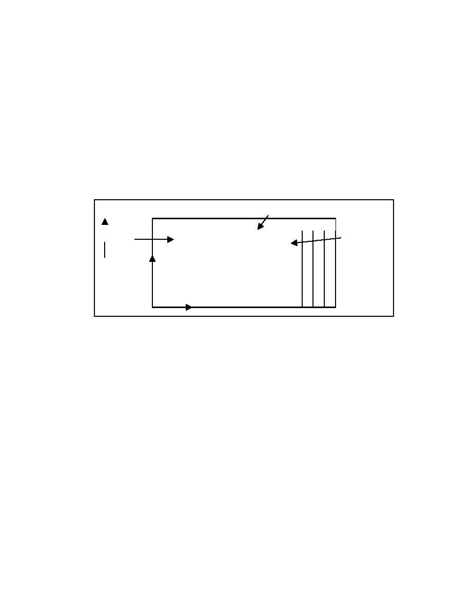
develop the input bathymetry. The grid domain is shown in Figure 16. The area
of interest is the eastern shoreline of the bay, where a project is planned to mine
sand to construct a beach. For a project such as this, wave information may be
required to evaluate sediment-transport rates at the borrow site to estimate
infilling rates or evaluate longshore and cross-shore sediment-transport rates at
the newly constructed beach to estimate the project's life and renourishment
requirements.
Grid Domain
15 10
5
N
wind
Borrow Site
X
(I=85, J=25)
y
x
Figure 16. Schematic of Example 2 grid domain
Model input
Model parameters. Both wave propagation and source terms (IPRP = 0) are
required for this example, but currents are negligible (ICUR = 0). Breaker
indices and radiation stress gradients are not required (IBREAK = 0 and IRS =
0). The special output points are selected to examine wave growth along the
major axis of the bay. The borrow site is located near grid cell (85,25). The
model parameter input file is:
0 0 0 0 10
5 25
25 25
50 25
75 25
85 25
95 25
97 25
98 25
99 25
100 25
55
Chapter 6 Example Applications


 Previous Page
