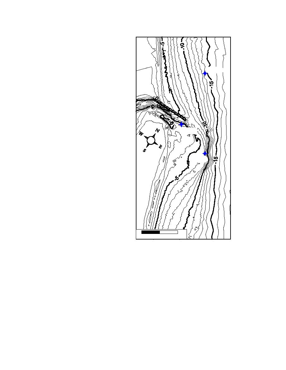
in Figure 11) was located near
this contour to provide the input
wave conditions. The lateral
boundaries of the domain are
positioned away from the
influence of the inlet, to areas of
DW G1
fairly straight and parallel depth
contours. A 50-m grid cell
spacing is selected to resolve the
ebb shoal and inlet bathymetry.
To cover the domain with 50-m
resolution requires 53 cells
across the shore (NI) and
112 cells alongshore (NJ).
Typical wave periods for this
site are 15 to 5 sec (0.0667 to
DW G3
0.2 Hz). To resolve this range,
30 frequency bins are used with
an initial frequency of 0.031 Hz
and a frequency increment of
0.0078 Hz (range of frequencies
DW G2
is 0.031 to 0.258 Hz). Because
the wave propagation distances
on the Ponce Inlet grid are short
(2 km), source terms are
neglected (IPRP = 1). Even
with strong winds, wave growth
over the short distance would be
small. Wave-current interaction,
though, could be significant near
the inlet, so ICUR = 1 to include
wave-current interaction is
selected. Breaker indices are not
saved (IBREAK = 0), and
0m
500 m 1000 m
neither are radiation stress
gradients (IRS = 0). Selected
Figure 11. Ponce Inlet bathymetry and
model output locations are
gauge positions
chosen to match three directional
wave gauge positions at Ponce
Inlet (see Figure 11). The depths at the three gauges are approximately 14, 7, and
5 m. The gauges are located near the offshore boundary, on the ebb shoal, and in
the outer inlet throat (north of the ebb shoal).
Bathymetry. The bathymetry contours for Ponce Inlet are shown in
Figure 11. The grid was developed using the SMS grid generator, which accepts
random x, y, and depth triplets and interpolates them onto a Cartesian grid with a
given origin, orientation, and resolution. In this case, high-resolution bathymetry
near the inlet was obtained from a Scanning Hydrographic Operational Airborne
Lidar System (SHOALS) (Lillycrop, Parson, and Irish 1996) survey and
supplemented with National Oceanic and Atmospheric Administration (NOAA)
50
Chapter 6 Example Applications


 Previous Page
