P. Wang et al. / Coastal Engineering 46 (2002) 175211
177
m high (Fig. 1). The unidirectional, long-crested
dominantly spilling breakers and one in plunging
irregular waves were produced by four synchronized
breakers over a fine-sand beach, were investigated.
wave generators oriented at a 10j angle to the shore-
Alongshore and cross-shore distribution patterns of
line. The beach was arranged in a trapezoidal plan
current and sediment concentration were measured.
shape corresponding to the obliquely incident waves
Vertical profiles of fluid velocity and sediment concen-
tration were also measured through the water column at
m3 of very well-sorted fine quartz sand with a median
frequencies of 20 and 16 Hz, respectively, allowing the
examination of temporal variations due to wave
grain size of 0.15 mm and a settling speed of 1.8 cm/s,
motion.
calculated based on Hallermeier (1981). The sand
The objectives of this paper are (1) to examine
beach was approximately 25 cm thick, placed over a
temporal and spatial variations of surf-zone currents
planar concrete base and extended 27 m alongshore
and suspended sediment concentration, (2) to estimate
and 18 m cross-shore. Fifteen meters of the beach was
the uncertainties associated with temporal and spatial
below the still-water level and the remaining 3 m was
averaging of the above parameters, (3) to investigate
above. The constructed topographic contours were
the uncertainties involved in the calculation of sedi-
reasonably straight and parallel with the shoreline.
ment flux using temporally and spatially averaged
The longshore current generated by the obliquely
current and concentration, and (4) to compare differ-
incident waves was circulated with 20 pumps through
ences in concentration and sediment flux between
dedicated flow channels from the downdrift end to the
predominantly spilling- and plunging-type breakers.
updrift end (Hamilton and Ebersole, 2001). The
influences of the lateral boundaries can be minimized
by properly circulating the wave-generated longshore
current. The present studies focus on the middle
2. The large-scale sediment transport facility
section of the test beach, where longshore uniformity
(LSTF)
in hydrodynamics and morphodynamics was approxi-
Detailed description of the LSTF is presented in
mated well.
The LSTF hosts a suite of instrumentation (Table
30-m cross-shore, 50-m longshore and has walls 1.4
1). Depth-integrated longshore sediment flux was
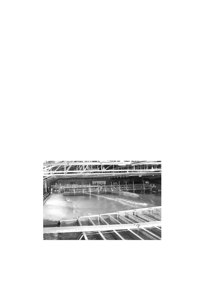
Fig. 1. The LSTF during the plunging case, showing the flow channels (bottom) and the instrument bridge (top) carrying the current meters and
wave gages (vertical rods).


 Previous Page
