1600
Spilling
1400
Plunging
1200
1000
800
600
400
200
0
0
5
10
15
20
Cross-shore location (m)
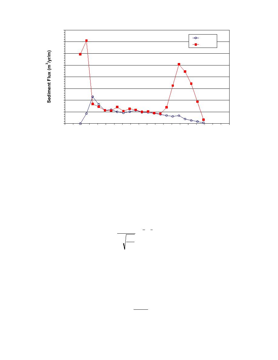
Fig. 5. Sediment flux distribution of spilling and plunging waves
surface in the bore. The jet associated with plungers penetrates deep into the water column
and causes sand to be suspended and transported by the longshore current. Through the
mid-surf zone, turbulence associated with broken plunging waves remains near the surface,
and transport is similar between breaker types. However transport in the swash zone is
substantially higher with plunging waves.
Comparison to Predictive Equations
Measured transport rates for the spilling and plunging case were compared to the CERC
formula (Shore Protection Manual 1984), and predictive equations of Kamphuis, et al.
(1986), Kamphuis (1991), and Kraus (1988). The CERC formula is given by:
3
5
K
ρg H sin(2θ b )
I=
(1)
2
2
b
Hb
16
hb
in which I is the submerged weight transport rate, K is an empirical coefficient
recommended by the Shore Protection Manual to be 0.39, Hb, hb, and θb are wave height,
due to gravity.
Kamphuis, et al. (1986) developed an empirical equation based on field data as:
H b .5 m
3
sin(2θ b )
Q = 1.28
(2)
d
Smith and Wang
1224


 Previous Page
