Summary and
minimization of the time required to
emptying valves and the lag
steady state. This valve scheme pro-
between initiation of the emptying
Conclusions
duced steady-state flow conditions in
valve operation were varied. The
about 23 min. Timings were rounded
pool conditions selected for this lock
This evaluation of the Lock 1 fill-
to the nearest 0.5 min. This resulted
operation optimization was an upper
pool elevation (el) 221.41 and a
ing and emptying system determined
in a filling valve operation time of
the discharge capacity of the lock
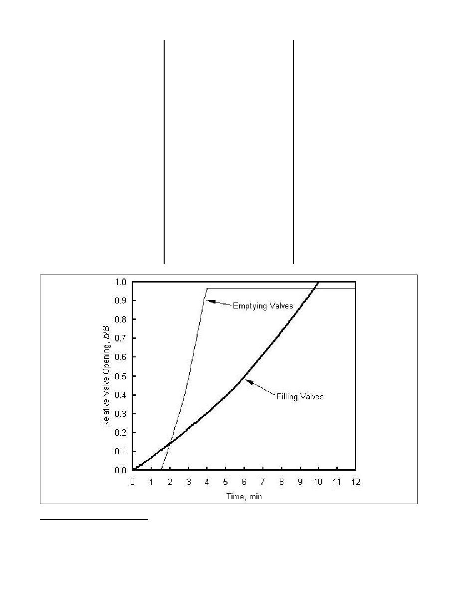
10.0 min, a 2.5-min emptying valve
lower pool elevation (el) 209.5. A
system with various valve and pool
opening time, and a lag of 1.5 min
total of 551 lock operation simula-
configurations. The discharge coeffi-
between initiation of the filling valve
tions found the optimum valve con-
cient of the lock system was deter-
and emptying valve operations
figuration that included minimization
mined to be 0.55 with the valve fully
(Figure 5). The results of these sim-
of the time required to reach the
open. The field data provided the
ulations are shown in Figures 6-8.
steady-state flow condition and that
information needed to validate the
The steady-state discharge at this
produced acceptable minimum cavi-
head is 93.5 m3/s (Figure 6) and the
numerical model. The numerical
tation indexes for both the filling and
model results indicate that steady
lock chamber water surface remains
the emptying valves. The optimum
flow through the lock system is best
at el 214.4 (Figure 7). The minimum
valve schedule used a 591.9-sec fill-
maintained with both the filling and
cavitation index downstream of the
ing-valve time, a 160.0-sec empty-
emptying valves fully opened. Valve
filling valves was 1.6 and the mini-
ing-valve time, and a 90.0-sec lag
operation optimization produced a
mum cavitation index downstream of
between valve operations. Both
valve schedule that provided accept-
the emptying valves was 0.71
exploitative and exploratory optimi-
able pressures below the valves
(Figure 8). This simulation demon-
zation techniques were used to glob-
while establishing the steady state
strates an operation schedule that
ally resolve the objective function,
most rapidly (about 23 min). The
meets the cavitation index guidance
which was maximization of the mini-
operation used 10-min filling valves,
for the low tailwater of el 209.5.
mum cavitation index and
2.5-min emptying valves, and a
1.5-min lag between initiation of the
filling valve and emptying valve
Figure 5. Valve schedule for establishment of steady flow, lock chamber initially empty
All elevations (el) cited herein are in meters referenced to the National Geodetic Vertical Datum.
1
42


 Previous Page
