ERDC/CHL CHETN-IV-61
December 2003
experiments collected data for the parallel jetty configuration. A short spur was then constructed
(46 m in length, if a 1:50 model to prototype scale is applied). A long spur of 76 m was also
constructed and a submerged version of this long spur was made by reducing the crest elevation
to mean low water while experiments were conducted at a +1.5-m elevation (again assuming a
1:50 model scale).
Figure 11 compares current patterns for these configurations. Red and green dye trace the current
patterns created by breaking waves and a flood tide maximum current. The deflection of the
wave-generated current by spurs in an upcoast direction is seen before it reverses direction sea-
ward of the spur, as the flood current entrains it. The submerged spur also deflects the longshore
current (Figure 11, bottom right). Waves break on the submerged spur, effectively deflecting the
longshore current and functioning similar to the emergent spur. A submerged spur is much less
costly to construct.
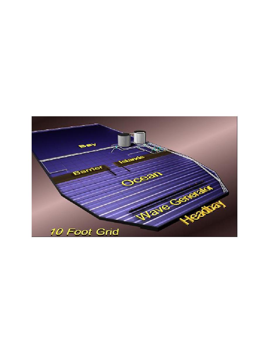
Figure 10. CIRP idealized inlet physical model
Figure 12 shows the results of sediment tracer experiments for the same wave and tidal current
conditions. The no-spur arrangement permits the tracer to enter the channel region. The short
spur reduces this transport somewhat and the longer spurs achieve better results, holding sedi-
ment in the region of the shoreward side of the spur.
Figure 13 shows detailed velocity fields in the region near the jetty for the four previously dis-
cussed model setups. An energetic wave (11-sec period, 3-m height) plus a maximum flood
current situation in the channel exist for these plots. Interesting to note are the current deflections
along the spurs and the increase in darker (slower currents) area regions, though changes are
small.
10


 Previous Page
