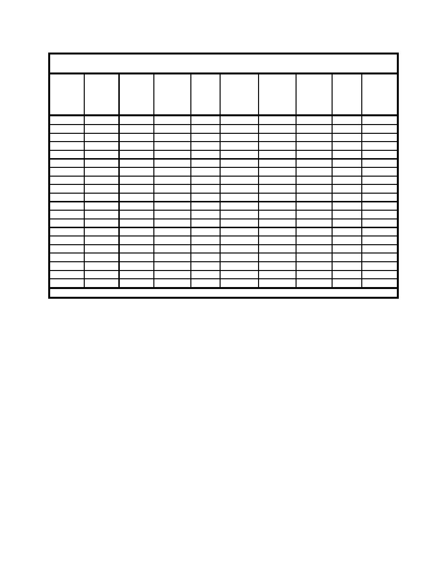
Table 3
Calculation of Discharge Rates for 20 Vertical Turbine Pumps
(1)
(2)
(3)
(4)
(5)
(6)
(7)
(8)
(9)
(10)
Pump or
Center
Initial
Measured
Ratio
Measured
Measured
Measured
Target
Pump
Flow
line
Beach
Average
-
MWL
Mean
Average
LSC
Discharge
Channel
X-Loc.
Profile
Profile
m
Water
c/s Area
m/sec
Rates
m2
No.
m
Depth
Depth
Depth
ℓ/sec
m
m
m
1
3.375
0.014
0.021
1.505
0.010
0.031
0.023
0.100
2.322
2
4.125
0.042
0.068
1.627
0.010
0.078
0.059
0.135
7.928
3
4.875
0.070
0.097
1.388
0.008
0.105
0.079
0.143
11.227
4
5.625
0.098
0.130
1.320
0.006
0.135
0.101
0.150
15.205
5
6.375
0.126
0.155
1.228
0.005
0.160
0.120
0.145
17.356
6
7.125
0.154
0.172
1.118
0.004
0.176
0.132
0.135
17.826
7
7.875
0.182
0.188
1.030
0.002
0.190
0.143
0.123
17.468
8
8.625
0.210
0.207
0.986
0.001
0.208
0.156
0.115
17.976
9
9.375
0.238
0.235
0.985
0.000
0.234
0.176
0.113
19.767
10
10.125
0.266
0.262
0.985
-0.002
0.260
0.195
0.115
22.455
11
10.875
0.294
0.289
0.983
-0.002
0.287
0.216
0.120
25.869
12
11.625
0.322
0.317
0.984
-0.002
0.316
0.237
0.120
28.401
13
12.375
0.350
0.344
0.980
-0.002
0.342
0.256
0.105
26.925
14
13.125
0.379
0.362
0.956
-0.002
0.360
0.270
0.080
21.595
15
13.875
0.407
0.372
0.916
-0.003
0.369
0.277
0.060
16.608
16
14.625
0.435
0.393
0.903
-0.005
0.388
0.291
0.040
11.627
17
15.375
0.463
0.435
0.941
-0.002
0.433
0.325
0.025
8.118
18
16.125
0.501
0.498
0.994
0.000
0.499
0.374
0.015
5.610
19
16.875
0.594
0.581
0.977
0.000
0.581
0.436
0.010
4.356
20
17.625
0.687
0.674
0.981
0.000
0.674
0.505
0.010
5.055
Total Longshore Flow Rate Actively Pumped through the External Recirculation System = 303.7 ℓ/sec
Column 6 lists the longshore averaged elevation of the mean water level
(MWL) as measured with the wave gauges at the six standard transects. These
values are measured relative to the still-water level. Column 7 is the measured
mean water depth, which was calculated by adding the values listed in Column 4
to those listed in Column 6.
Column 8 is the longshore averaged cross-sectional area of the water column
in front of each flow channel (i.e., the cross-sectional area of the water column in
front of each flow channel in which the longshore current flows downstream).
These values are obtained by multiplying the values in Column 7 by a factor of
0.75 m, which is the width of each flow channel.
Column 9 lists the cross-shore distribution of the depth-averaged longshore
current, to be pumped through the lateral boundaries of the facility. These values
are obtained using the procedure developed for establishing uniform longshore
currents which is discussed in detail in Chapter 9.
Finally, Column 10 is the pump discharge rates, for each of the 20 vertical
turbine pumps, required to recirculate the target cross-shore distribution of the
mean longshore current through the lateral boundaries of the facility. The pump
discharge rates are obtained in liters/second (from cubic meters/second) by
multiplying the product of the values in Column 8 and Column 9 by a factor of
69
Chapter 7
Wave Generation and Current Recirculation


 Previous Page
