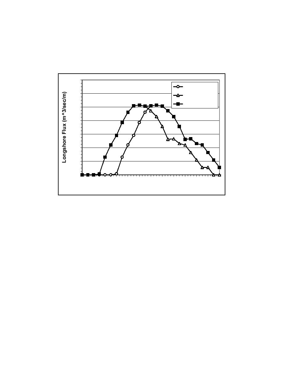
the slope of the concrete beach is 1:30. The third curve in the figure
encompasses both the first and second curves and represents the required
pumping capacity of the LSC recirculation system for water levels ranging from
0.9 to 1.0 m. As shown in the figure, incorporating a variable water level into the
design essentially broadens the width of the LSC distribution that needs to be
recirculated within the facility.
0.14
Depth = 0.9 m
0.12
Depth = 1.0 m
Upper Limit
0.10
0.08
0.06
0.04
0.02
0.00
0
2
4
6
8 10 12 14 16 18
20
22
24
Cross-shore Location (m)
Figure 14. Influence of water depth on required longshore current distribution
Design Pumping Capacity
The last step in this phase of the design process was to determine the design
capacity of each of the individual pumps that make up the LSC recirculation
system. Required pump capacity is a function of the width of the flow channels
at the downdrift end of the facility, which is directly related to the cross-shore
resolution of the LSC recirculation system. Intuitively, one would expect that the
higher the cross-shore resolution, the longer the "testing region" where longshore
uniformity of waves and wave-driven longshore currents exist. After reviewing
the designs of LSC recirculation systems used in other laboratory facilities, it was
decided that the flow channels at both ends of the LSTF should be 0.75 m in
width. This was a compromise between cross-shore resolution and the estimated
cost of construction.
Knowing the required pumping capacity of the LSC recirculation system,
shown as the upper limit in Figure 14, and given a flow channel width of 0.75 m,
the capacity of each individual pump could be readily calculated. Figure 15
shows a bar graph expressed in litres/sec for every 0.75-m width of surf zone,
and the magnitude of each bar represents the required pumping capacity of each
individual pump. To reduce the number of pumps near the shoreline, where the
24
Chapter 3
Longshore Current Recirculation System


 Previous Page
