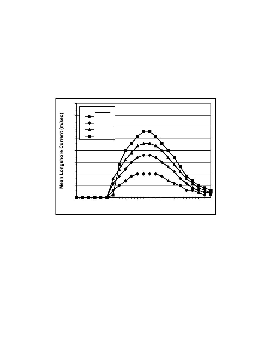
Influence of incident wave direction
Figure 13 shows the LSC distribution for θ = 5, 10, 15, and 20 deg with
Hs = 0.3 m and Tp = 2.5 sec. Three general trends can be seen in this figure.
First, as θ increases, the magnitude of the LSC at the peak of the distribution
significantly increases. The magnitude of the peak LSC equals 0.10, 0.18, 0.23,
and 0.28 m/sec for θ = 5, 10, 15, and 20 deg, respectively. This is a relative
increase of about 80, 28, and 22 percent for each consecutive increase in θ.
Secondly, the cross-shore location of the peak of the LSC distribution remains
constant as θ increases. Thirdly, the width of the LSC distribution remains
reasonably constant as θ increases.
0.40
θ
0.35
5 deg
10 deg
0.30
15 deg
20 deg
0.25
0.20
0.15
0.10
0.05
0.00
0
2
4
6
8
10
12
14
16
18
20
22
Cross-shore Location (m)
Figure 13. Influence of wave direction on required longshore current distribution
Based on these numerical simulations, it was concluded that increasing Hs
strongly influences the magnitude and cross-shore location of the peak of the
LSC distribution, whereas, increasing Tp has a much milder effect. In addition,
increasing θ has a very strong influence on increasing the peak magnitude but no
influence on the cross-shore location of the peak of the LSC distribution.
Design Parameters
The first part of this section describes the design wave condition used to
determine the required pumping capacity of the LSC recirculation system.
Subsequent sections apply a factor of safety to the numerical model results, and
incorporate the requirements of conducting experiments with a moveable-bed
beach and a variable operating water level into the design.
21
Chapter 3
Longshore Current Recirculation System


 Previous Page
