Fundamentals of Engineering Design
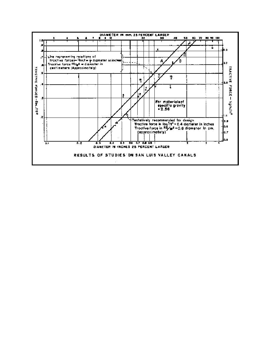
Figure 5.32 Variation of Tractive Force With Bed Material d (from Lane, 1953a)
6.
Evaluate K from Figure 5.31. Knowing K and the critical tractive force acting on the bed,
the tractive force on the sides can be computed.
7.
Enter Figure 5.30 and determine the maximum tractive force in terms of D So acting on the
8.
Equate from step 6 to C D So and knowing C, the slope So can be evaluated.
9.
Compare the slope based on bed stability, step 4, with slope based on side stability, step 8,
whichever is smaller governs.
10. Check the capacity of the canal using the established slope and assumed shape. If the
capacity is incorrect, assume a new shape and repeat the above procedure. This process
continues until a satisfactory design results.
The following limitations of the maximum allowable velocity and tractive force design procedures
are as follows (USACE, EM 1110-2-1418, 1994):
163


 Previous Page
