Fundamentals of Engineering Design
It is not the force on a single particle but rather the force exerted over a certain area of the bed or
banks. It is equal to and in the opposite direction from the force which the bed exerts on the flowing water.
It is the force which is the component, in the direction of flow, of the weight of water (Lane, 1953b). The
weight force is equal to ALSf , where: is the specific weight of water, A is the cross-sectional area, L
is the length of the channel reach, R is the hydraulic radius, P is the wetted perimeter, and Sf is the slope
of the energy grade line. The average value of the tractive force per unit wetted perimeter or the unit
tractive force is given by the following equation (Simons and Sentrk, 1992):
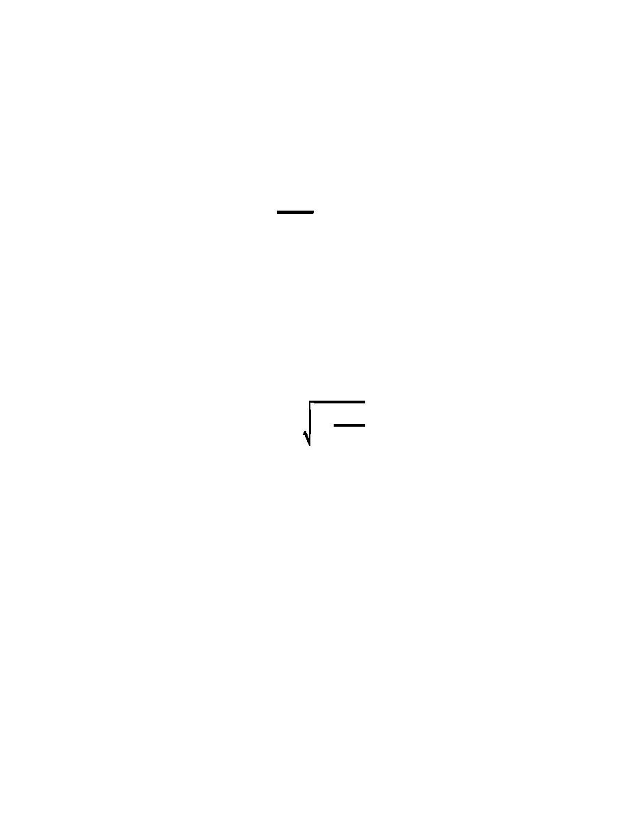
(ALSf
' (RS f
Jo '
(5.3)
PL
Lane shows that in most canals, similar to those used for irrigation, the tractive force near the middle
of the channel invert closely approaches D So, where: D is the hydraulic depth of the channel, and So is
the slope of the bed assuming uniform flow. His results indicate that for trapezoidal channels the maximum
shear on the sides is approximately 0.75 D So as illustrated in Figure 5.29. Figure 5.30 shows the
maximum shear for the sides and the bottom of trapezoidal sections in a graphical format. Lane found the
side slopes of a channel posed limitations on the maximum allowable shear force in the channel. He
analyzed the shear and gravity forces acting on a sediment particle on the canal side slope to quantify these
effects. K is defined as the ratio of the tractive force necessary to start motion on the sloping side of a
canal, to that required to start motion for the same material on a level surface as the following (Lane,
1953b):
2
tan N
K ' cos N
1&
(5.4)
2
tan 2
where:
=
the angle with the horizontal of the side slope of the canal; and
=
the angle with the horizontal of repose of the material.
Lane presents a graphical representation of this equation as seen in Figure 5.31. Simons (1957)
provides a detailed process for Lane's tractive stress method.
Tractive Force Design Procedure (Simons, 1957)
1. Knowing Q and d75, assume a shape.
2. Calculate a width to depth ratio, B/D, based on assumed shape. Enter Figure 5.30 with this
where: c
=
critical tractive force;
C
=
friction coefficient;
=
specific weight of water;
D
=
hydraulic depth of channel; and
=
So
bed slope.
160


 Previous Page
