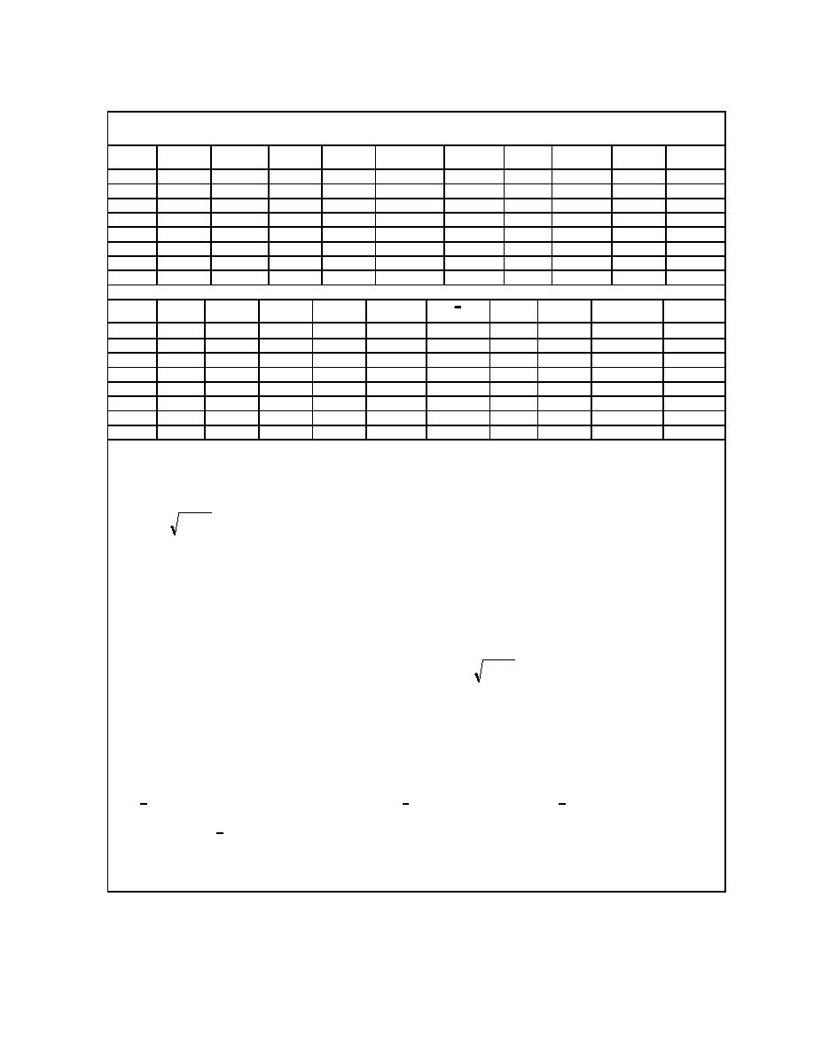
Table 4.8. Hydraulic Calculations for Sample Problem 3. Application of the Einstein
Procedure (after Einstein 1950).
"
"
"
X
V
V/V *
V*
R′b
V′*
δ′
ks/δ′
∆
Ψ′
Rb
1
2
3
4
5
6
7
8
9
10
11
0.5
0.129
0.00095
1.21
1.59
0.00072
2.92
2.98
16.8
0.17
0.86
1.0
0.184
0.00067
1.72
1.46
0.00078
4.44
1.49
27.0
0.16
0.76
2.0
0.259
0.00047
2.44
1.27
0.00091
6.63
0.75
51.0
0.13
0.50
3.0
0.318
0.00039
2.95
1.18
0.00097
8.40
0.50
87.0
0.10
0.30
4.0
0.368
0.00033
3.50
1.14
0.00101
9.92
0.37
150.0
0.07
0.14
5.0
0.412
0.00030
3.84
1.11
0.00104
11.30
0.30
240.0
0.05
0.07
6.0
0.450
0.00027
4.26
1.08
0.00107
12.58
0.25
370.0
0.03
0.03
2
y = Rb
Stage
A
Pb
Rb
Q
PE
Y
(β/βx)
βx
X
12
13
14
15
16
17
18
19
20
21
22
1.36
1.36
150.2
140
103
410
0.00132
0.84
1.29
0.63
10.97
1.76
1.76
150.9
240
136
1,065
0.00093
0.68
1.19
0.85
11.10
2.50
2.50
152.1
425
170
2,820
0.00069
0.56
0.91
1.27
11.30
3.30
3.30
153.3
640
194
5,380
0.00075
0.55
0.91
1.27
11.40
4.14
4.14
154.9
970
234
9.620
0.00079
0.54
0.91
1.27
11.70
5.07
5.07
156.9
1,465
289
16,550
0.00084
0.54
0.91
1.27
11.90
6.03
6.03
159.5
2,400
398
30,200
0.00082
0.54
0.91
1.27
12.04
Notes:
(1) R′b ft (bed hydraulic radius due to grain roughness), values are assumed to cover the entire desired discharge
range
'
(2) V′* =
gR b S fps (shear velocity due to grain roughness)
(3) δ′ = 11.6ν / V′* ft (thickness of laminar sublayer)
(4) ks = D65, ft (roughness diameter)
(5) X = f (ks/δ) (correction factor in the logarithmic velocity distribution), given in Figure 4.7
(6) ∆ = ks/X ft (apparent roughness diameter)
(7) V = V′* 5.75 log (12.26 R′b /∆ fps (average flow velocity)
(8) Ψ′ = (ρs - ρ /ρ ) (D35 /R′bS) (intensity of shear on representative particles), given by Equation 4.44
"
(9) V/V * = f (Ψ′) given in Figure 4.11
"
(10) V * fps (shear velocity due to form roughness)
"
(11) R"b ft (bed hydraulic radius due to form roughness) from V"* =
gRbS
(12) Rb = R′b + R"b ft (bed hydraulic radius), with no additional friction from the banks, Rb represents the total
hydraulic radius R
(13) y ft (average flow depth), y ≈ Rb for wide shallow streams
(14) Stage, ft, from description of cross section, Figure 4.19 for R = Rb.
2
(15) A, ft , (cross-sectional area), from Figure 4.19 for the given stage
(16) Pb ft, (bed wetted perimeter), from Figure 4.19 for the given stage
(17) Q = AV cfs (flow discharge), a stage-discharge relationship can be plotted by relating the
computed Q to the stage
(18) X ft (characteristic distance), from Equation 4.36, X = 0.77∆ for ∆/δ′ > 1.80 and X = 1.39δ′ for ∆/δ′ < 1.8
(19) Y = f (ks/δ′) (pressure correction term), given in Figure 4.8
(20) β x = log (10.6 X /∆), (logarithmic function)
(21) β = log 10.6
(22) PE = 2.303 log (30.2 y /∆), (Einstein's transport parameter), given by Equation 4.32
4.47


 Previous Page
