ERDC/CHL CHETN-III-69
March 2004
1
0.8
0.6
0.4
0.2
0
A
B
C
D
E
F
Configura tion
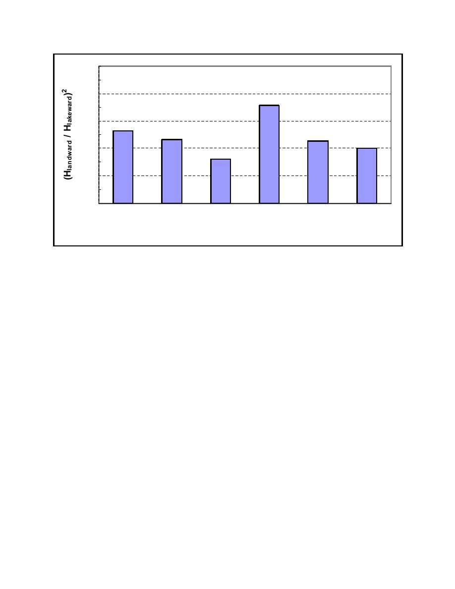
Figure 5.
Wave energy fraction passing pocket for various pocket configurations; average from three
incident wave directions studied in physical model (prototype dimensions)
However, F is not as effective as C for 30-deg wave direction. This behavior can be attributed to the
pocket geometry of configuration F, which affords wave energy approaching at 30 deg a fairly clear
path to reflect off the jetty walls and avoid direct impact with either pocket. The same process
appears to be detrimental to the performance of configuration E for 15-deg wave direction.
BACKGROUND, FIELD STUDIES: The University of Michigan, Department of Civil
Engineering, study also included a limited field measurement effort to supplement the physical
model studies (Carpenter 2001). Field investigations were conducted at Pentwater and White Lake
Harbors, Lake Michigan. Similar data also were obtained at Ontonagon Harbor, Lake Superior,
during one week in November 2000 by Michigan Technological University, Department of Civil and
Environment Engineering, as part of this effort. Pentwater has two 59.4-m- (195-ft-) long pockets
opposite each other in a 44.2-m- (145-ft-) wide channel, similar to configuration C in the physical
model experiments (Figure 6). White Lake has a similar configuration with 53.9-m- (177-ft-) long
pockets. Ontonagon has a different configuration and wider channel (76.2-m (250-ft) wide).
Ontonagon data were collected to quantify the effect of a single 61-m- (200-ft-) long pocket,
comparable to configurations A and B in the physical model experiments.
Strengths and limitations of the field investigations are summarized in Table 2. Wave heights were
measured adjacent to one of the jetties on lakesides and landsides of the pocket by submerged
pressure transducers. Due to logistical problems with collecting data during periods of high wave
energy at the Lake Michigan sites and lack of directional incident wave data at all sites, results are
6


 Previous Page
