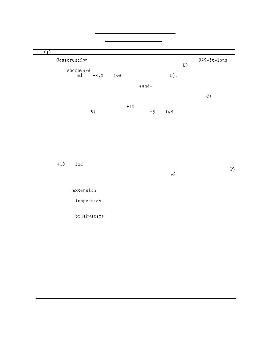
Table 73
Port Sanilac Harbor Breakwaters
Port Sanilac, Michigan
Date
Construction and Rehabilitation History
1951
of a 1,230-ft-long north breakwater and a
south breakwater (Figure 195, Types A, B, C , and
was completed.
The
ends of both structures consisted of steel sheetpiling
Riprap was placed on
of
ft
(Figure 196, Type
with an
the lakesides of the structures. The remaining portions of the
breakwaters were constructed of
and gravel-filled cellular
steel sheet-pile structures with cell diameters ranging from 2 3 . 8 7
.
(Figure 196, Type A) to 28.85 ft (Figure 196, Types B and
The
Type C structure at the lakeward end of the north breakwater (Fig-
ure 1 9 6 ) had a crest el of
ft lwd, and the remaining portions
crest el. Riprap was
(Types A and
were installed at a
ft
placed on both sides of the lakeward portion of the north breakwater
(Type C) and on only the lakesides of the cells of the remaining
structures (Types A and B.
)
The cells were capped with asphalt.
1975
To reduce wave heights in the harbor to approximately one-half foot,
a 327-ft-long extension to the north breakwater and a 69-ft-long ex-
tension of the south breakwater (Figure 195, Types E and F) was com-
pleted. The north breakwater extension consisted of stone-filled,
steel sheet-pile cells with a diameter of 4 3 ft and a crest el of
(Figure 196, Type E. The south breakwater extension was
)
ft
constructed of stone-filled cellular sheet piles (Figure 196, Type
ft lwd. The exten-
sions were capped with bituminous concrete. Riprap stone ranging
from 1,000 lb to 1 ton was placed on both sides of the north break-
water
and on the lakeside of the south extension.
A site
of the structures revealed that some of the asphalt
1984
caps of the north breakwater had settled, but the breakwaters were
generally in good condition. An aerial view of the Port Sanilac
Harbor
is shown in Figure 197.
298


 Previous Page
