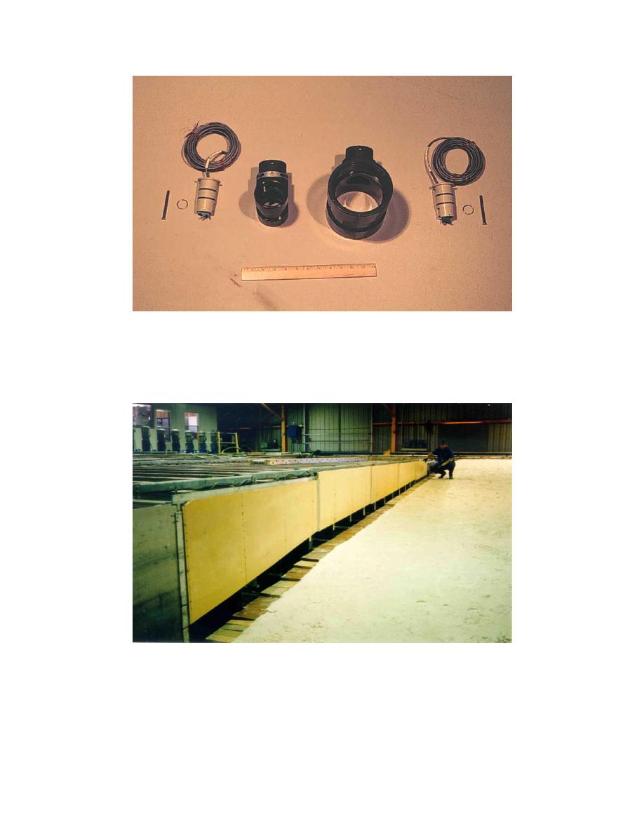
Figure B8. Pump No. 10 forces through either a 50- or a 100-mm-diam in-line
flow sensor. The forward-swept design of the impellers, as well as
the absence of magnetic drag, provides improved accuracy and
repeatability at low flow rates. A 0.3-m-long wooden ruler indicates
the physical size of the components
Figure B9. View of the wave guide at the downstream end of the beach. The
bottom edge of the wave guide was installed at approximately the
minimum wave trough elevation for the maximum wave condition
that can be generated in the facility. Hence, the height of the
opening beneath the wave guide increases in the offshore direction
B5
Appendix B
Photographs of the Large-scale Sediment Transport Facility


 Previous Page
