30
Y16
25
Y20
Y24
Y30
20
LB's
15
10
5
0
-5
-10
0
5
10
15
20
Cross-shore Location (m)
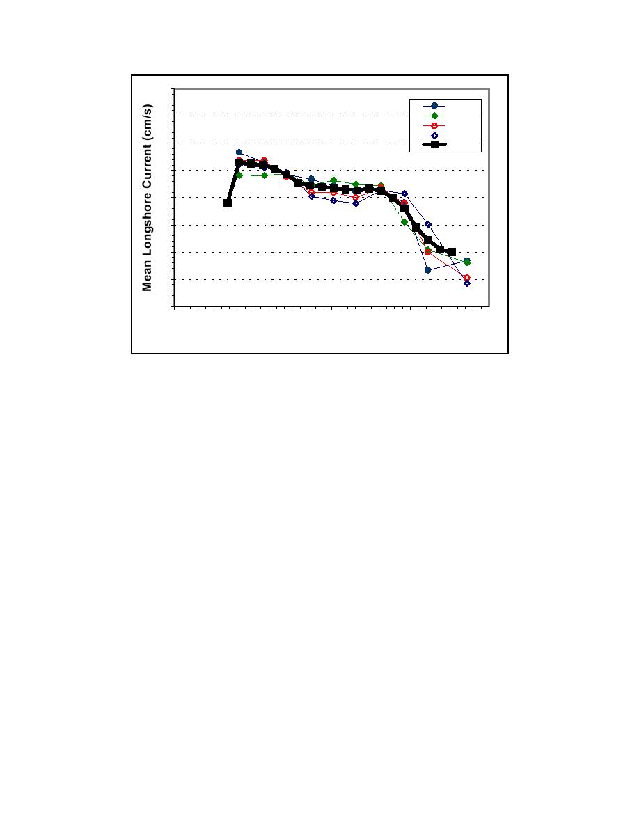
Figure 88. Alongshore variation in mean longshore current for the plunging-
breaker case
Sediment concentration
Figures 89 and 90 illustrate the degree of alongshore uniformity in measured
sand concentration for the spilling- and plunging-breaker cases, respectively.
Both the top and bottom panels of each figure show the temporally averaged
sediment concentration (a mean computed for a 10-min record) as a function of
elevation within the water column at a number of transects along the beach.
Measurements were repeated three times at each transect for the spilling breaker
case, and those data also are shown in Figure 89. At each alongshore position,
concentrations are given for two locations, one in the incipient breaker zone (top
panel in each figure), and one in the midsurf zone (bottom panel in each figure).
Note that the vertical axis is plotted using a logarithmic scale.
For the spilling-breaker case, concentrations varied by 20 to 40 percent of the
mean value in the alongshore direction for measurements made in the zone of
incipient wave breaking. Variability was higher in the midsurf zone, with
variability ranging from 30 to 90 percent of the mean. A similar result was found
for the plunging-breaker case. In the incipient breaker zone, variations were
generally 10 to 30 percent of the mean, with variability approaching 50 percent
for a few sensors. In the midsurf zone, variability generally ranged from 30 to
45 percent of the mean, with some sensors differing by as much as 120 percent
(near the surface in this instance). Variability in measured mean concentration is
much higher than variability in gross wave and current parameters. This suggests
that concentration measurements from a number of transects should be averaged,
144
Chapter 10
Longshore Sediment Transport Experiments


 Previous Page
