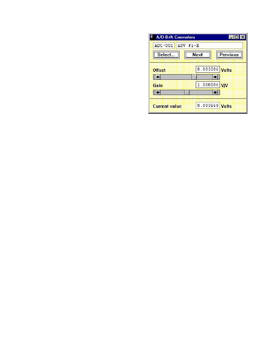
Next, the ADV system is forced to output
5.000 V, and, the value of the gain is
adjusted if the analog-to-digital converter
does not read exactly 5.000 V. This
procedure is repeated for the 38 ADV
channels. This calibration process
requires approximately 1 hr and should be
checked on a monthly basis to compensate
for significant changes in ambient
temperature.
Measurement of currents
The ADVs can be accurately
Figure 45. A/D-D/A converters panel in the
positioned at any x-y location within the
MTS control software is used to
testing region of the facility, as is the case
adjust the gain and offset values for
for the wave gauges. The procedure used
the ADV analog output signals
to measure currents is essentially the same
(Permission to reprint granted by
as that used to measure waves. In
MTS Systems Corp.)
Figure 40, the ADVs are evenly distributed
every 1.5 m along the bridge, so that 10 ADVs cover a total range of 13.5 m in
the cross-shore direction. The longshore position of the ADVs is selected from
the control room by moving the instrumentation bridge to the desired transect
location.
identical to that used to measure waves because one of the objectives is to
synchronize the wave and current measurements. In addition, the 38 ADV
analog signals are recorded using the same Data Recorder panel in the MTS
control software as the wave gauges, shown in Figure 42. Therefore, the
sampling frequency and duration are the same for both wave and current
measurements.
The orientation of the ADVs is critical. However, because of the high-
quality mounting devices that were built to mount the ADVs to the bridge, this
issue only needs consideration when one or more of the ADVs are repositioned
along the bridge. Upon initial installation of the ADVs, the y-axis was accurately
aligned to be parallel with the longitudinal axis of the bridge. When an ADV is
relocated along the bridge, the alignment of the vertical mounting struts, and
hence, the orientation of the ADV is verified. The mounting mechanism ensures
that the ADV does not rotate with respect to the vertical strut. The orientation of
each ADV can be verified during a tow-tank experiment. If the ADVs have the
proper orientation, the cross-shore velocities should be essentially zero as the
bridge traverses along the support rails.
Seeding material and SNR
To ensure that high-quality velocity data are collected using the ADVs, a
minimum SNR of 10 to 15 decibels (db) is to be maintained throughout the
sampling duration. The SNR is monitored using the real-time display system for
the ADV digital data, shown in Figure 38. The ADV velocity data appears
80
Chapter 8
Sensor Calibration, Measurement, and Data Analysis


 Previous Page
