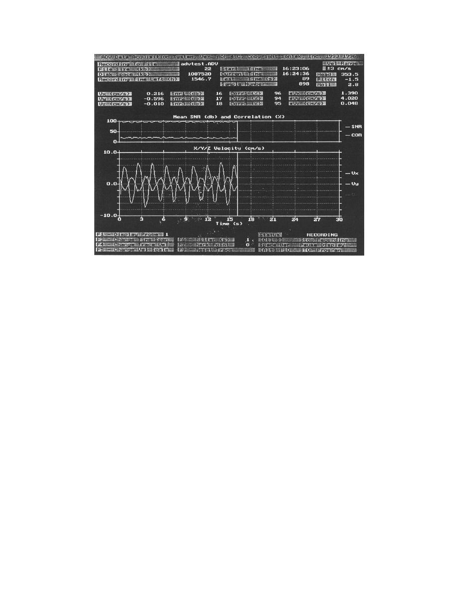
Figure 38. Real-time display screen for ADV digital data (Permission to reprint
granted by SonTek 1997) (SonTek and ADV are registered
trademarks of SonTek/YSI Inc., San Diego, CA, USA)
Control System for Vertical Turbine Pumps
As discussed in Chapter 3, the speed of the 20 vertical turbine pumps is
controlled using 20 variable frequency motor controllers. These motor
controllers are housed in a building adjacent to the LSTF control room. The
standard input frequency to a motor controller is 60 Hz. The speed of the pumps
is controlled by adjusting the output frequency of the motor controllers, using a
human interface module located on the front of each motor controller, shown
previously in Figure 17. The output frequency can be adjusted from 30 to 100
percent of the input frequency (i.e., output frequency = 18 to 60 Hz). Because
there is a linear relationship between output frequency, pump speed, and pump
discharge, the discharge from the pump can be controlled from 30 to 100 percent
of the maximum discharge rate. A detailed description of how to operate the
motor controllers can be found in, Allen-Bradley (1996).
Each of the motor controllers were equipped with optional serial
communication modules to provide a direct digital link between the 20 motor
controllers and a personal computer. Control software could be developed that
would allow the operator to enter the required discharge rates into the computer,
and the software would calculate the output frequency for each motor controller
based on the relationship between output frequency and pump discharge,
previously shown in Figure 19. The control software would then adjust the
output frequency of the motor controllers, based on the difference between the
measured flow rate and the required flow rate. This would automate the present
method of manually iterating to the required pump settings. Furthermore, using a
61
Chapter 6
Experiment Control, Data Acquisition, and Analysis Packages


 Previous Page
