

D.G. Hamilton, B.A. Ebersole r Coastal Engineering 42 (2001) 199218
216
Table A-2
Primary data set from irregular wave Test 8E
havg Zm.
Vavg Zmrs.
d Zm.
Hmo-avg Zm.
X-Loc. Zm.
Y19 Zmrs.
Y23 Zmrs.
Y27 Zmrs.
Y31 Zmrs.
4.12
0.188
0.227
0.207
0.154
0.194
0.037
0.016
0.053
5.72
0.303
0.326
0.316
0.306
0.313
0.091
0.013
0.082
7.12
0.326
0.341
0.333
0.346
0.337
0.137
0.006
0.107
8.62
0.297
0.313
0.298
0.309
0.304
0.187
0.001
0.138
10.12
0.270
0.277
0.267
0.267
0.270
0.237
y0.001
0.167
11.52
0.228
0.233
0.226
0.221
0.227
0.284
y0.004
0.185
13.12
0.337
y0.008
0.206
13.88
0.122
0.128
0.121
0.125
0.124
0.363
14.62
0.387
y0.009
0.214
16.12
0.038
0.012
0.010
0.031
0.023
0.437
y0.010
0.224
16.85
0.462
y0.008
0.227
18.00
0.500
y0.007
0.232
Table A-3
Summary of wave and water level conditions in the surf zone
g
u br
hm
Hbr
hbr
Hbrrhbr
X br
Test
X-Loc.
X-Loc.
at hm Zm.
Z8.
Zm.
Zm.
Z.
Z.
Zm.
Zm.
at SWL Zm.
Test 6N
0.254
0.274
0.93
0.74
6.7
11.5
0.033
2.1
3.00
Test 8E
0.206
0.329
0.63
0.75
7.3
13.1
0.021
2.4
3.00
surf zone averaged value of Hrh, and the subscript,
For the regular wave case, the breaking point is
AbrB, refers to values at the breaker line. The break-
assumed to be the point where the measured wave
ing wave angle, u br , was estimated using Snell's
height reaches its maximum value. For the irregular
law.
wave case, the breaking point was assumed to be the
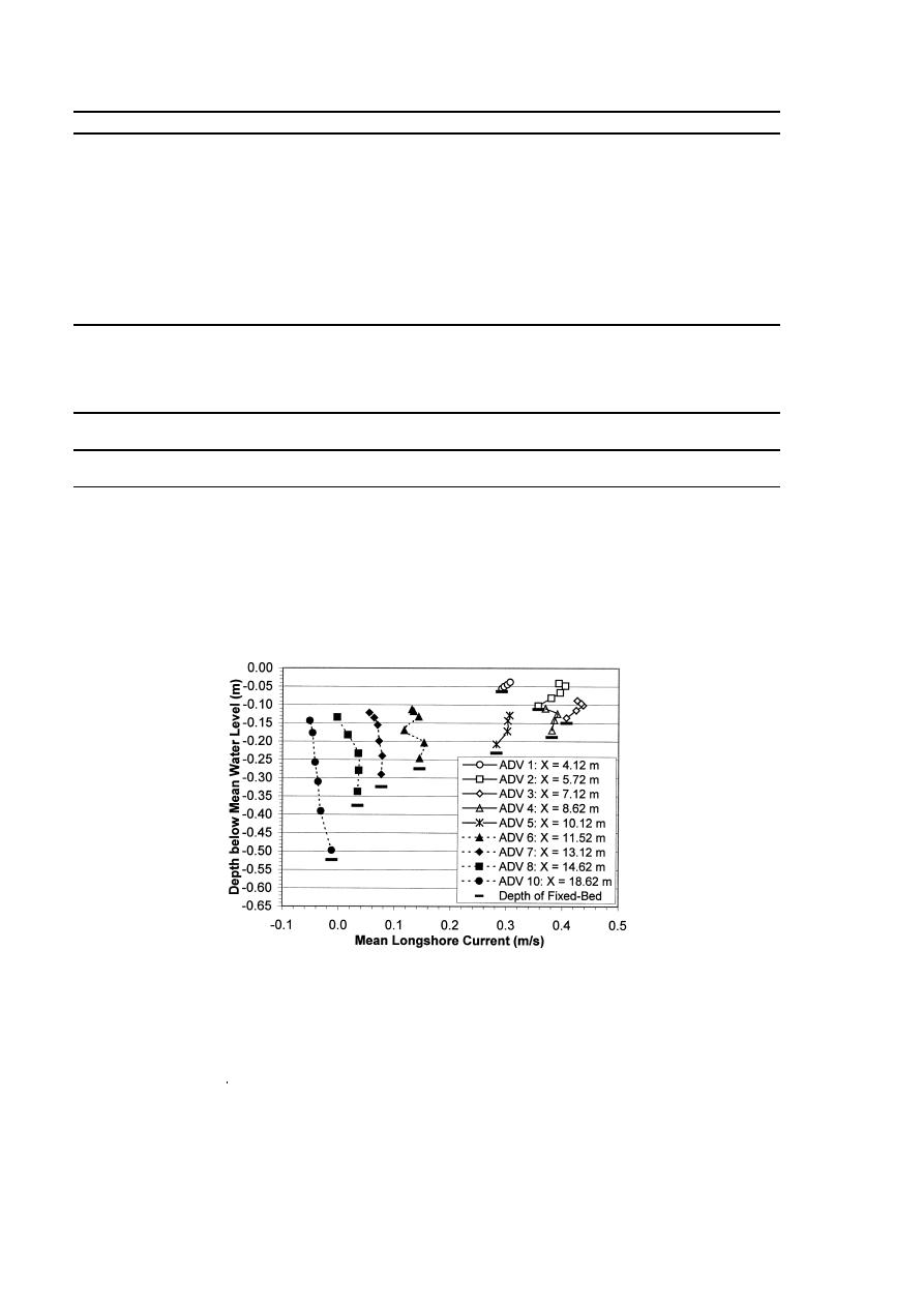
Fig. B1. Regular wave Test 6N: vertical structure of the mean longshore current at Y27.

 Previous Page
