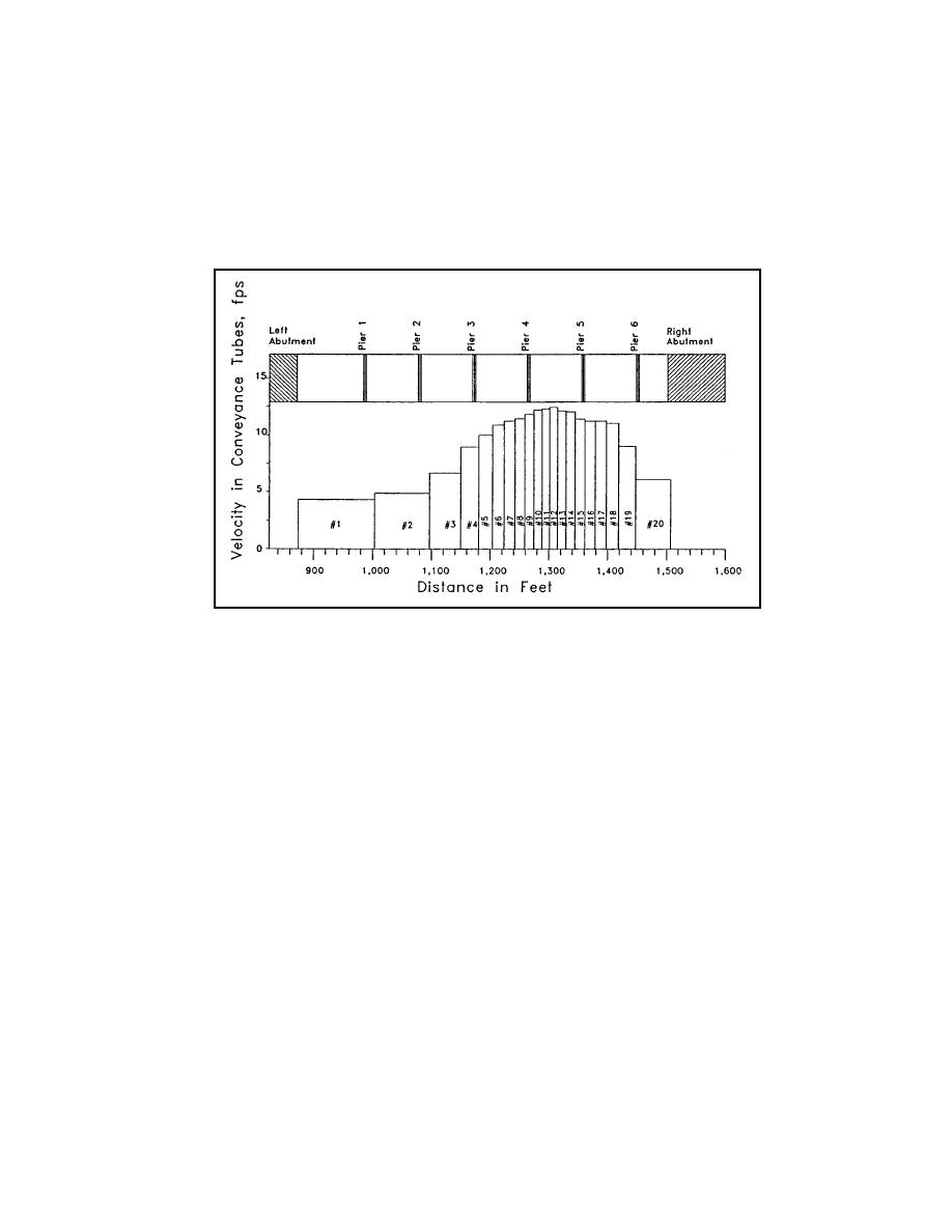
The hydraulic variables used to estimate the local scour at the piers were determined from a
plot of the velocity distribution derived from the WSPRO output (Figure 10.31). For this
example the highest velocities and flow depths in the bridge cross section were used (at
conveyance tube number 12). Only one pier scour computation was completed because the
possibility of thalweg shifting and lateral migration requires that all of the piers be set
assuming that any pier could be subjected to the maximum scour producing variables.
Figure 10.31. Velocity distribution at bridge crossing.
equations presented in Section 7.8.
10.3.4 Level 2 - Scour Analysis Results
Use of the hydraulic data from the WSPRO model in the appropriate equations of Chapter 7
resulted in the following scour estimates:
Live-bed contraction scour in main channel (Equation 7.2) - 9.2 ft (2.8 m)
Clear-water contraction scour on left overbank (Equation 7.4) - 1.7 ft (0.52 m)
Local scour at piers (Equation 7.7, 0 angle of attack) - 11.8 ft (3.6 m)
Local scour at piers (Equation 7.7, 10 angle of attack) - 19.3 ft (5.9 m)
Local scour at left abutment (Equation 7.21) - 8.4 ft (2.6 m)
Local scour at right abutment (Equation 7.21) - 13.3 ft (4.1 m)
The results of the scour computations should be plotted on the bridge cross section and
carefully evaluated (Figure 10.32). For this example, only the computations for pier scour
with piers aligned with the flow were plotted. The topwidth of the local scour holes is
estimated as 2.0 times the depth of scour.
10.43


 Previous Page
