ERDC TN-DOER-T6
September 2004
Rullens (1993) reports that the half-ball and centrifuge method has several advantages:
Construction is simple.
The system is essentially maintenance-free.
The system can be made operational quickly.
The system is inexpensive.
Measurements are reasonably accurate.
Disadvantages of the half-ball and centrifuge method include:
The contractor is not paid for increasing the load's density over 1.2 s.g.
What the measured volume actually represents is not known.
The liquefied load samples must be consolidated, so results are not immediately known, and
feedback to optimize the loading process is not available.
Results are affected by human influence.
Bin manual sounding methods.
Bin manual sounding measure-
ment methods are similar to
hopper manual sounding methods
described above to determine the
volume of dredged material being
transported.
One significant
difference between sounding a
hopper or bin is that cohesive
sediment loaded by a mechanical
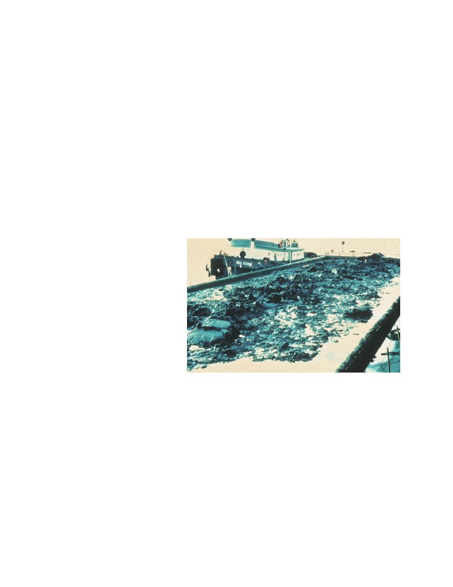
dredge can be mounded up in the
bin (Figure 3). With this situation,
measurement error is related to
the volume of material mounded Figure 3. Mounded dredged material in bin
above (or below) the averaged
height of material calculated by multiple soundings of the bin.
Hopper level sensors. Hopper content volumes can also be measured by the use of level-
sensing devices usually installed over the hopper (Figure 4). As with manual sounding, hopper
material volume is calculated by applying the sensor-measured average material level to the
hopper capacity table. Ultrasonic level-sensing sensors have been used by the dredging industry
since the 1980's (Rokosch 1989). These hopper-level sensors consist of ultrasonic transducers
that emit acoustic waves and detect the energy that's reflected from the dredged material surface.
Similar to a hydrographic survey, the distance between the transducer and acoustic reflector is
based on the time interval required for the acoustic energy to travel from the transducer, bounce
off the hopper material, then return back to the transducer. Figure 5 shows an ultrasonic
transducer mounted over the dredge McFarland's hopper. Two of these programmable sensors
were mounted on each end of the McFarland's hopper as close to the hopper centerline as
7


 Previous Page
