

ERDC/CHL CHETN-I-66
June 2002
3
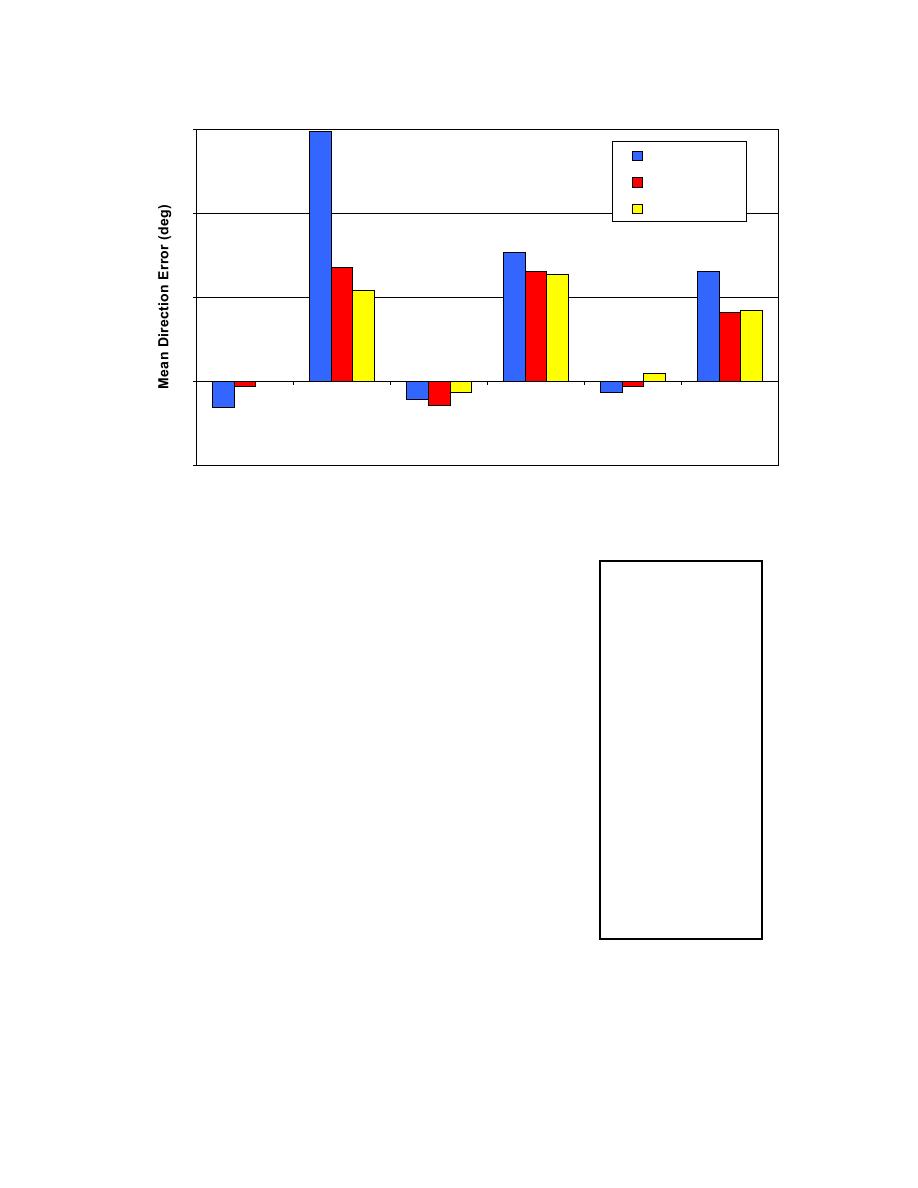
Coarse Grid
Linear
Morphic
2
1
0
Bias (large shoal) RMS Error (large
Bias (med shoal)
RMS Error (med Bias (small shoal) RMS Error (small
shoal)
shoal)
shoal)
-1
Figure 8. Wave direction error for coarse grid and with nesting using linear and morphic interpolation
Model Parameter File. A sample model parameter file for
1 0 0
0 2 0
the coarse grid runs used in the examples is given in Figure 9.
10 7
The first line in the file is the model parameters (detailed
11 7
descriptions are given by Smith, Sherlock, and Resio 2001):
17
9 1
9 2
IPRP = 1 for propagation only, 0 for wind source terms
9 3
ICUR = 1 for wave-current interaction, 0 for no currents
9 4
IBREAK = 1 to print indices for breaking, 0 to not print indices
9 5
IRS = 1 to calculate radiation stresses, 0 to not calculate
9 6
stresses
9 7
9 8
NSELCT = number of output spectral points
9 9
IBND = 0 for single point boundary input, 1 for linear boundary
9 10
interpolation, and 2 for morphic boundary interpolation. IBND
9 11
is a new STWAVE input that is required in Version 4.0. A
9 12
value of IBND = 0 is used for the coarse offshore grid, and a
9 13
9 14
value of 1 or 2 is used for a nested grid.
9 15
9 16
Following the model parameters are the I,J locations for saving
9 17
wave spectra (NSELCT paired values). The last section of the
parameter file is the optional output locations for grid nesting.
Figure 9. Sample offshore
This is new in Version 4.0. The first number is the number of
coarse grid options file for
output nesting points (NEST), and it is followed by NEST
nested grids
paired I,J locations where spectra are saved for grid nesting. In
the sample file in Figure. 9, NEST = 17 and the nesting output
is saved along the entire ninth column of the coarse grid. The
7

 Previous Page
