CETN IV-19
March 1999
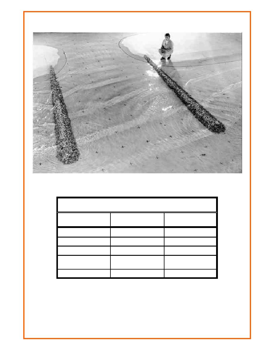
Figure 2. Idealized inlet entrance channel
Table 1
Model-Prototype Scale Relations
Model-Prototype
Characteristic
Dimension
Scale Relation
Length
L
Lr = 1:50
L2
Ar = Lr2 = 1:2,500
Area
L3
Vr = Lr3 = 1:125,000
Volume
Tr = Lr1/2 = 1:7.07
Time (tidal and short
T
wave period)
Velocity
L/T
Vr = Lr/Tr = 1:7.07
releasing it back to the bay to flow to the ocean during ebb flow. Pumps and control valves
associated with this procedure are located adjacent to the storage tanks.
system is shown in Figure 1. Water is either collected (flood flow) or distributed (ebb flow)
3


 Previous Page
