

D.G. Hamilton, B.A. Ebersole r Coastal Engineering 42 (2001) 199218
202
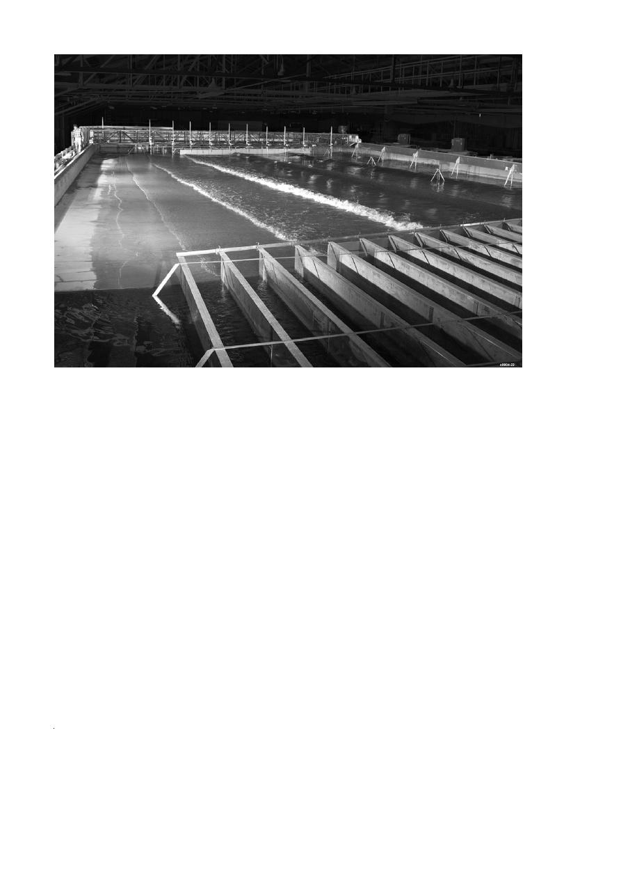
Fig. 1. Oblique view of the Large-scale Sediment Transport Facility Zregular wave experiment.. A technician standing in the upper left
corner indicates the physical size of the facility.
based on future plans to extend the length of the
wide. This design allows a large range of longshore
wave basin. However, for the sake of simplicity, all
current magnitudes and cross-shore distributions to
downstream-directed longshore current speeds and
be accurately controlled and externally recirculated.
flow rates presented in the paper are given as posi-
Hamilton et al. Z1997. provides design details for
tive numbers, even though the flow is in the negative
each of the primary components in the recirculation
y direction.
system.
The external recirculation system consists of 20
Design of the upstream and downstream lateral
independent pump-and-piping systems with a total
boundaries was a challenge since the longshore cur-
capacity of 1250 lrs. Hamilton et al. Z1996. describe
rent has to flow out of and into the flow channels
the methodology used to determine the capacity and
while wave diffraction into the flow channels needs
functional requirements of this system. Twenty flow
to be minimized. Waveguides were designed so that
channels at the downstream end of the facility guide
the height of the opening beneath the waveguide
the longshore current from the beach to the pumps
could be adjusted to allow the longshore current to
Zsee Fig. 2.. Likewise, on the upstream end, 20 flow
pass beneath the impermeable waveguide. For the
channels guide the flow from the point of pipe
wave conditions and water level used during these
discharge to the upstream boundary of the beach.
experiments, the height of the opening was selected
Flow channels extend from x s 3.0 to 18.0 m in the
after several trial and error iterations. At the up-
cross-shore direction, and each channel is 0.75 m
stream boundary a constant 0.1-m high opening be-

 Previous Page
